This is a continuation in a series of posts on power consumption in the Sony a7RII. The more recent incarnation of the series starts here.
I’ve been telling you all about what I’ve been finding out about the a7RII battery draw under various conditions. It’s time I showed you how I’m doing the testing. Warning: if you don’t know the first thing about electricity and electronics, this won’t mean a lot to you.
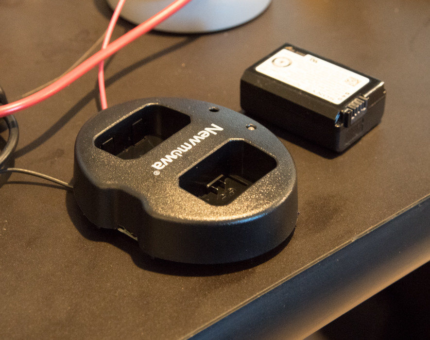
I’m powering the camera with a regular Sony battery that’s been removed from the camera so that I can look at the current. I started out with a a7x USB battery charger:
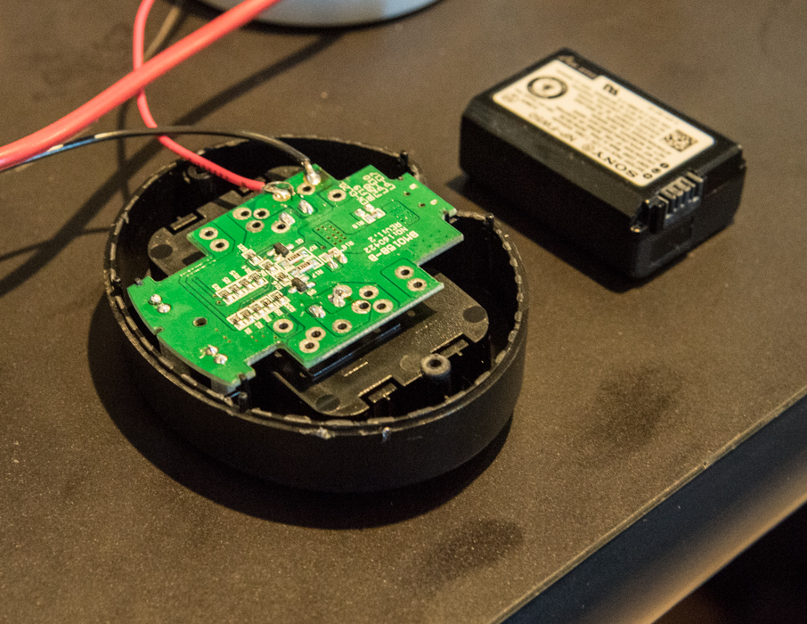
Then I modified it so that I could get at the battery terminals:
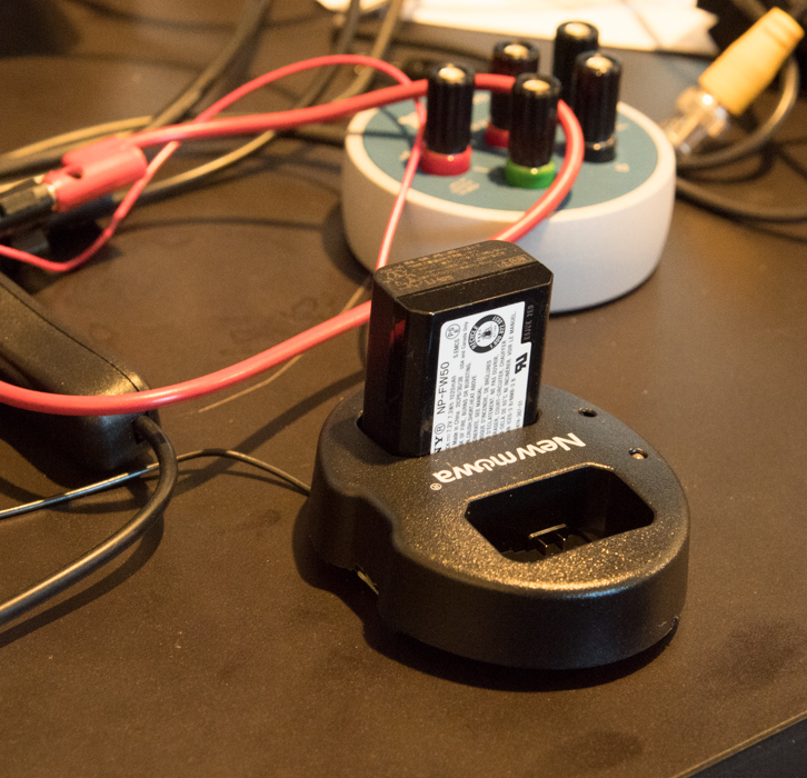
To power the camera, I plug the battery into the charger socket:
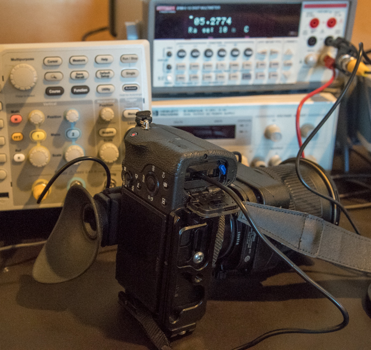
Then I plug the output of the charger into the camera with one of the leads running through the Keithley Digital Multimeter (DMM) set to the 1 amp scale, which gives a series resistance of 0.1 ohm:
The multimeter is at the upper right. It’s sitting on an hp power supply that I was using before I decided to use a real battery. To the left in the background is the oscilloscope I use for examining rapid dynamic current behavior. The ‘scope reads the voltage across the 0.1 ohm resistance of the DMM.
Now I’ll show you a technique that I’ve developed over the last few days to get cleaner traces with the scope, whose lowest-bandwidth setting is 20 MHz. First, I’m using a 0.1 ohm (more or less; it’s not critical since I’m doing waveform captures, not current measurements with the ‘scope; I’ve go the DMM for that) nichrome wire shunt in place of the meter to shorten up on the leads:
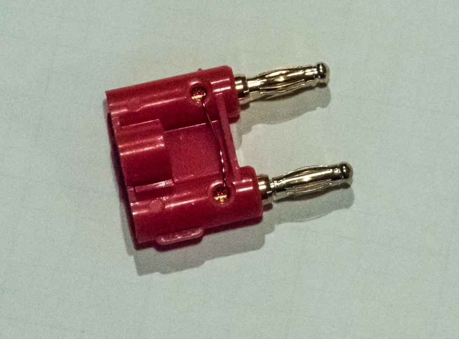
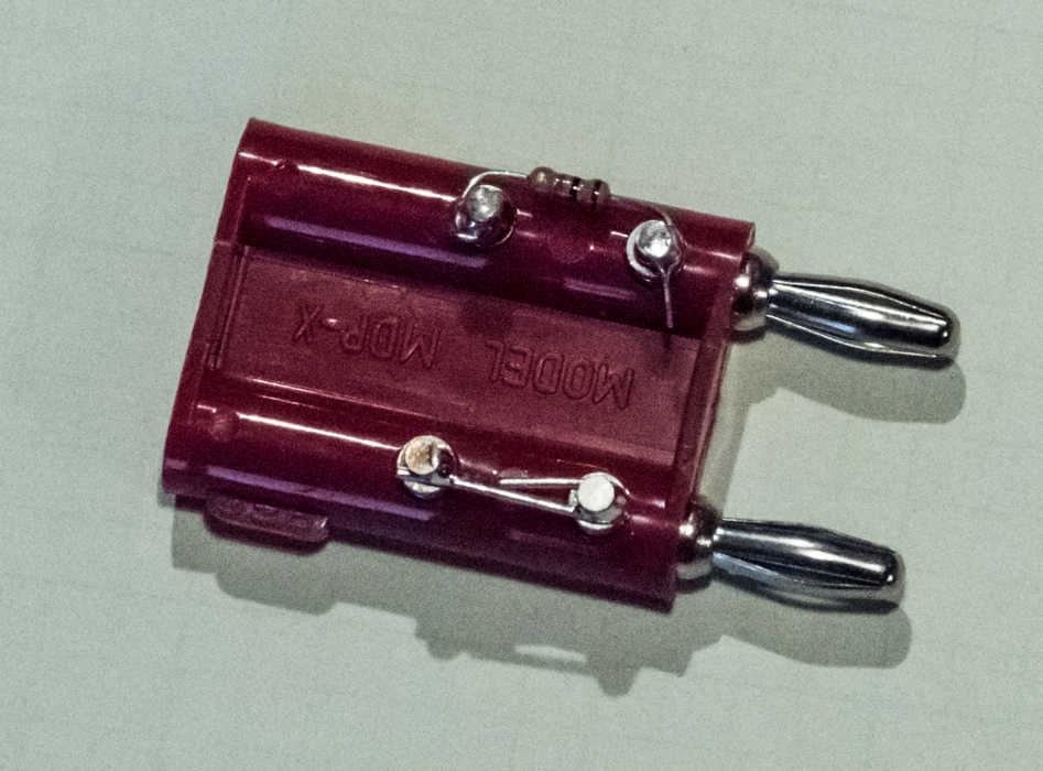
I plug a couple of banana leads into the shunt, and run them to a 1 K ohm series resistor:
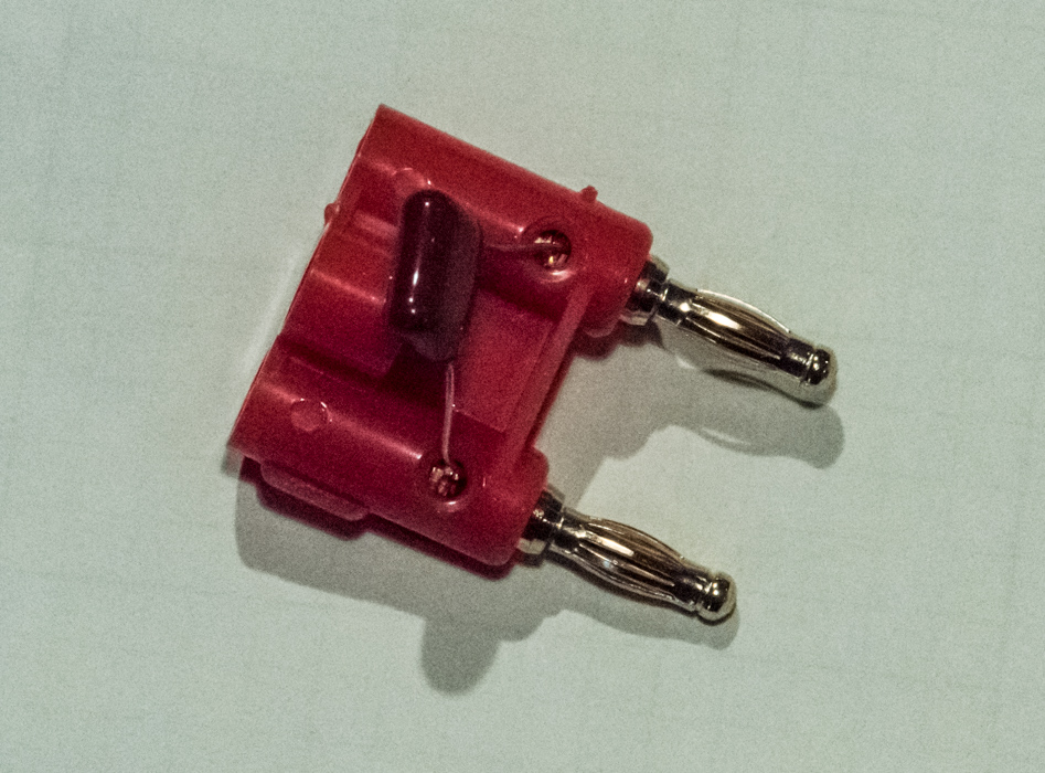
And then to a 0.01 microfarad capacitor to ground:
I used to have the cap on the same assembly as the 1K resistor, but I’ve separated the two to make it easy to change capacitance, and thus rise time.
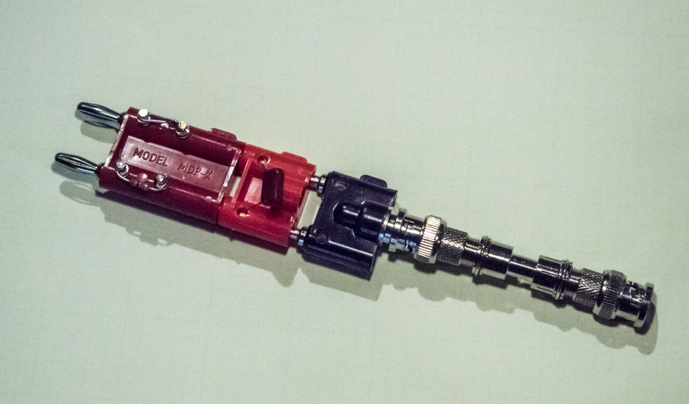
When all this stuff is plugged together along with some kleudged-together BNC gender-changing hardware, it loks like this:
The right-side end ot the above assembly plugs into the ‘scope, and the left side is connected via two banana leads to the 0.1 ohm shunt.
The result is a lower-bandwidth signal at the scope, and far less noise and aliasing. It works pretty well. I’ll show you some results soon.
[…] at the end of a post about my battery current testing methodology, I showed you my new technique for relatively high-speed dynamic measurements. Today, I’ll […]