In analyzing the photon transfer performance of a digital camera, it is usual to construct a model of the camera’s imaging properties, and then determine the parameters of these properties should the camera under test conformed to the model. It is also useful to know those areas for the camera does not work as the model says it should.
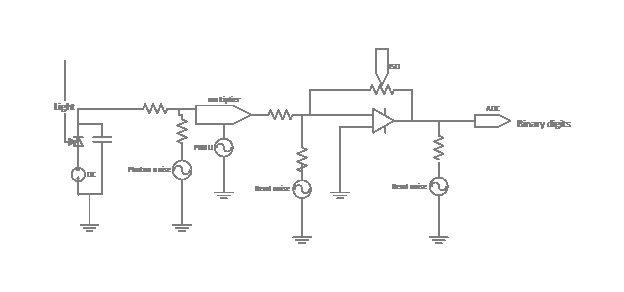
Here is the model that I’m using:
For the most part, this models a single pixel. There is one important deviation from that, and I’ll explain that when I get to it.
Let me walk you through the model.
Light falls on a back-biased photodiode, causing electrons to accumulate on the plate of a capacitor. Because of the physics of light, there is noise – called photon noise — associated with that process. You can consider the charge on the capacitor to be the sum of a DC – zero frequency – signal measured in electrons, and a Gaussian noise source whose standard deviation is the square root of the DC signal. This noise source, like all the others in the model, are sampled once per exposure.
The next noise source is photon response nonuniformity a.k.a. photo response nonuniformity, a.k.a. PRNU. Rather than adding to the DC signal, this can be thought of as multiplying it by a number whose mean is one and whose standard deviation is a measure of the PRNU. This is the part where the single pixel model breaks down, since PRNU is usually a fixed pattern error, and for any particular pixel, there is no noise. In fact, I would be happy to not consider it noise at all, but the convention is to do so, and in this instance I will go with conventional wisdom.
There is an amplifier between the capacitor and the analog-to-digital converter. The gain of the amplifier is determined by the ISO setting in the camera. There are a group of noise signals that don’t vary with the number of electrons on the capacitor. These signals are referred to collectively as readout noise, or simply read noise.
There are three ways to model read noise. The first is to measure it for each ISO setting as if it all occurred before the amplifier. In this case the units for read noise are electrons. The second way is to again measure it for each ISO setting, as if it all occurred after the amplifier. In this case the units are usually specified in terms of the least significant bit of the entity converter. The third way is to measure the noise at all ISO’s, compute the gain of the amplifier for each one, and calculate what must be the value of the preamplifier read noise and the post amplifier read noise. The Matlab model does the first and the third calculation.
The analog-to-digital converter is assumed to be perfect. To the degree that it is so, the quantization noise introduced by the ADC is part of the post amplification read noise. To the extent that the ADC introduces noise because of its imperfections this is also part of the post amplification read noise.
With the exception of PRNU, and any part of the read noise that doesn’t change from exposure to exposure, the single pixel model can be used to explain noise within a single image, by assuming that every pixel in the camera behaves identically, so the exposure to exposure noise of the single pixel model turns into variation among the pixels of a single capture.
Tomorrow: the sensor characterizer in action.

Leave a Reply