In a comment to a recent post, Jack Hogan posted this link.
It’s well worth reading. In it you’ll find Frans van den Bergh’s explanation of how a 4-way Lithium Niobate beam-splitting anti-aliasing (AA) filter works, and what convolution kernel simulates one that has 0.375 pixel shifts.
I added that kind of AA filter to the model.
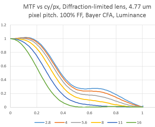
Here’s what the simulator says the luminance MTFs of a diffraction-limited lens look like from f/2.8 to f/16 with a 4.77 micrometer (um) Bayer color filter array (CFA) sensor with 100% fill factor and no AA filter:
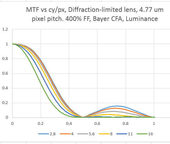
Here’s what it looks like at 400% fill factor:
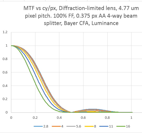
And here it is with 100% fill factor and a 0.375 pixel 4-way beam splitter:
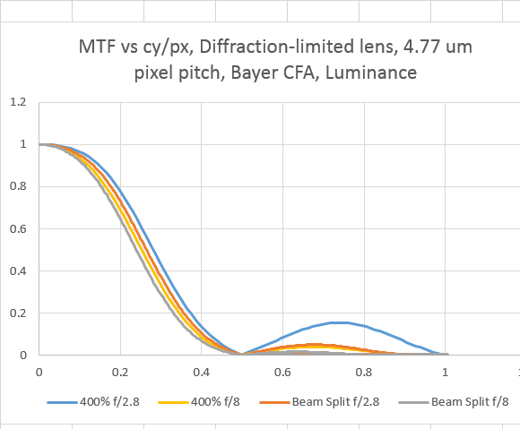
The beam splitter is better than the 400% fill factor at attenuating the unwanted energy at spatial frequencies over the Nyquist frequency. How does it compare in the pass band? Let’s have a look at both for f/2.8 and f/8:
At both f-stops, the beam splitter is a little worse in the pass band, but better in the stop band. Until that wonderful day when we’ll have enough resolution in our sensors to image everything our lenses can deliver, the beam splitter doesn’t look so bad. I’ll be doing some simulation runs with variable sensel pitches in the future to get an idea of the tradeoffs.


Jim, looks good. Only question I have is about the zero at 100% FF, which in your graph appears to hit the axis at around 0.5 cycles/pixel.
As far as I can remember the 4-dot beam splitter MTF formula is abs(cosine(2.pi.s.x)), with s the frequency in cycles per pixel and x the +/- shift introduced by the splitter in pixels. That function hits a first zero at pi/2, which would correspond to 0.667 cycles/pixel when x=0.375 pixels.
Yes, and I’m getting a zero at 0.5. I noticed that discrepancy, but haven’t tracked it down. I’m not doing my sim in teh frequency domain, but rather by using convolution kernels.
Jim