This is a continuation of a series of posts on the Nikon D850. The series starts here. You should be able to find all the posts about that camera in the Category List on the right sidebar, below the Articles widget. There’s a drop-down menu there that you can use to get to all the posts in this series; just look for “D850”
Yesterday, I showed you that, with the Sigma 85 mm f/1.4 Art, the AF Adjust setting on the D850 that gives the right average correction for an object on the lens axis (in the center of the finder), gives approximately correct values when the subject is off axis. But there was quite a bit of focus shift, and it was hard to tell if the depth of field (DOF) available at narrower stops would be sufficient to cover up the systematic focusing errors that would occur if you set the AF Adjust parameter to be correct when the lens is wide open (which is what most people recommend doing).
To refresh your memory, here’s the setup:
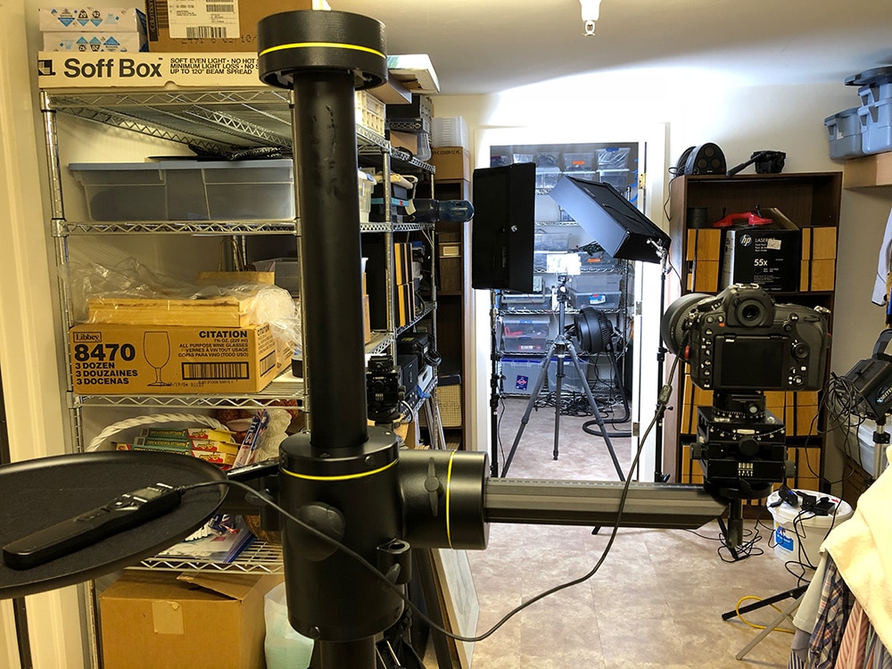
The camera is focused on the LensAlign flat plate to the left of the ramp. I make a set of phase detection autofocus (PDAF) exposures at various f-stops (shown here) and sometimes AF Adjust values (not shown in this post). I make 10 exposures for each test condition. I also make 32 exposures using CDAF and use those to calibrate out small alignment errors.
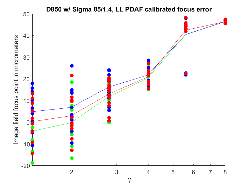
I have been presenting the results like this:
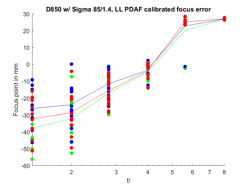
This shows how the plane where the lens focuses on the subject (this is called the object field by photo geeks like me). Negative values mean that the lens focuses ahead where it should; this is known as front-focusing. Positive values mean that the lens focuses behind the intended spot; this is known as back-focusing. This is pretty intuitive but has a couple of problems.
The first is that it’s not easy to relate the shifts to other focal lengths and other target distances. The second is that it’s not at all obvious how much blur results from, say, 1 centimeter of defocus. Is it a little? A lot? You’d have to pull out your DOF tables to find out.
My first thought was to get away from the object field and report the errors in terms of shifts of the focal plane as projected on the sensor. This is known to the photo-cognoscenti as the image field.
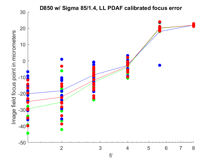
Now we’ve taken the focal length and target distance out of the picture so that it’s easy to compare lenses of different focal lengths at different distances. However, this has come at some cost; the dimensions of the vertical axis are totally foreign to most photographers. Is 10 micrometers (um) of shift a little or a lot?
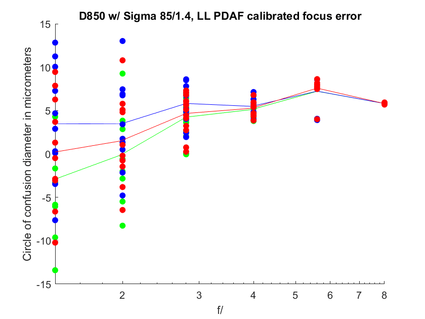
Last night, I came up with another way to present the data:
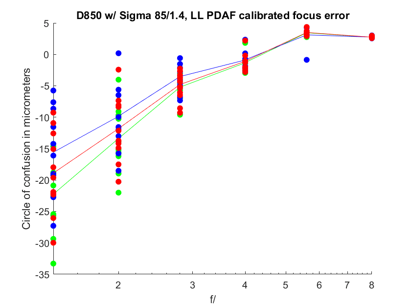
Now we’re looking at something that most serious photographers, at least those with any kind of technical bent, are quite familiar — the diameter of the circle of confusion (CoC) on the sensor due to misfocussing. There is a curveball, however. Front-focusing and back-focusing both produce circles of confusion with positive diameters. In fact, the concept of a negative diameter for the CoC kind of boggles the mind. Nevertheless, that’s how I’ve chosen to represent the CoCs that result from front-focusing. The ones that come from back focusing have positive diameters.
What CoC diameter is OK? It all depends. For critical sharpness, you want a CoC on the order of the pitch of the sensor, which in the case of the D850 is 4.34 um. You can see that the spread of all the samples at f/4 through f/8 in the above chart pass that test, and the average error for the f/2.8 sample set comes close. Back in the film days, a CoC of 30 um used to be considered acceptable; that’s the standard that’s used in calculating the DOF indicators engraved into manual focus lenses (Don’t get me started on the DOF scales on AF lenses). If 4 um is a high CoC bar, 30 um is a really low, but well-known, one.
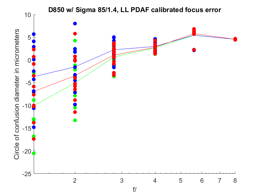
What if we used an AF Adjust value optimized for f/1.4 for this lens? That would amount to moving the image field numbers by 25 um. If we did that, we’d get something like this for image field focusing:
And the CoC diameters would look like this:
To me, it looks like if you wanted 1-pixel-pitch-or-less CoCs at all apertures with one AF value, you could come pretty close undercorrecting this lens at f/1.4 by about 10 um in the image field. That would mean that the average f/1.4 exposures would be off far enough to give you an unacceptable CoC (by this tough standard), but the spread at f/1.4 is all over the place so you will get the average error infrequently.
Here’s what that would look like:
I think in the future, I’m going to concentrate on the image field and CoC graphs. Between the two of them, it should be possible to AF tune a lens without many — or any — iterations.
Arthur says
Seems a little more tweeking and this works. (12?) It’s natural that you’ll have a greater spread at 1.4 and 2 so if you can get 2.8 and 4 to come down a little bit more and perhaps close to equal at 0 you will have the best performance possible across the stops.
Any idea why the 1 set of values at 5.6 is so far off ?
The last problem – how to get this to where most people can use it.
Andre Y says
Jim, how do you compute the image field shift from the object field shift? Is it from a purely geometric analysis? Eg. 105mm at 10 ft at f/1.4 means the projected image will change this much for an object field movement of so much?
And is the CoC calculation just dividing the image field shift by pi, or is it something more complicated?
JimK says
Yes.
It’s more complicated. The aperture figures into the calculation.
Andre Y says
Thanks. The reason I ask is when I was looking at your latest Sony lens measurements, it occurred to me that the measured shifts were much smaller than the sensor’s pixel size, so it had to be derived from something else to be valid.
JimK says
The source is the location in the image of the sharpest portion of the FocusAlign ramp.