This is one in a series of posts on the Fujifilm GFX 100S. You should be able to find all the posts about that camera in the Category List on the right sidebar, below the Articles widget. There’s a drop-down menu there that you can use to get to all the posts in this series; just look for “GFX 100S”. Since it’s more about the lenses than the camera, I’m also tagging it with the other Fuji GFX tags.
One of the objections to the series of tests of the GF lenses that I’m doing is that all the testing is done on the lens axis, or in the center of the frame. The reason for that has been the difficulty of doing some of the tests off-axis, but now that I’m coming to the end of the on-axis testing, it’s time to explore what I can do off axis.
Here’s the test protocol:
- RRS carbon fiber legs
- C1 head
- Target distance 9.7 meters for a 110 mm lens
- ISO 100
- Electronic shutter
- 10-second self timer
- f/2 through f/11 in whole-stop steps
- Exposure time set by camera in A mode
- Focus bracketing, step size 1, 80 exposures
- Initial focus well short of target
- Convert RAF to DNG using Adobe DNG Converter
- Extract raw mosaics with dcraw (I’ll change this to libraw and drop the DNG conversion when I get the chance, but the Matlab program that controls all this is written for dcraw)
- Extract slanted edge for each raw plane in a Matlab program the Jack Hogan originally wrote, and that I’ve been modifying for years.
- Analyze the slanted edges and produce MTF curves using MTF Mapper (great program; thanks, Frans)
- Fit curves to the MTF Mapper MTF50 values in Matlab
- Correct for systematic GFX focus bracketing inconsistencies
- Analyze and graph in Matlab
I analyzed a horizontal edge in the center of the frame, and both a horizontal and a vertical edge on the far right side of the frame. The horizontal edge is oriented in a radial direction, and that’s how I’m identifying it in the plots. The horizontal edge is oriented in a tangential direction, and that’s the way I’m tagging it.
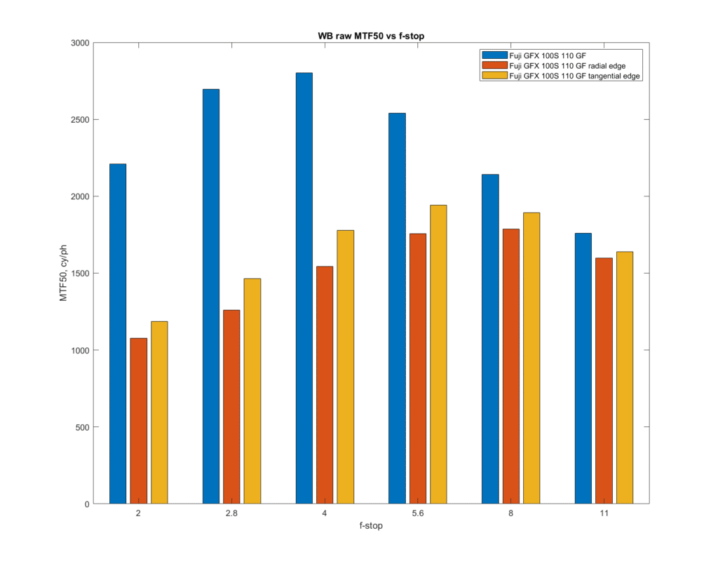
Here are the MTF50 results, in cycles per picture height.
I measured the MTF50 on each of the raw channels, and am reporting on the MTF50 on a white-balanced composite of those channels, which is mostly the green channel. Wide open, the 110 GF is about half as sharp on the edge as it is in the center. The best compromise f-stop seems to be f/5.6 or f/8.
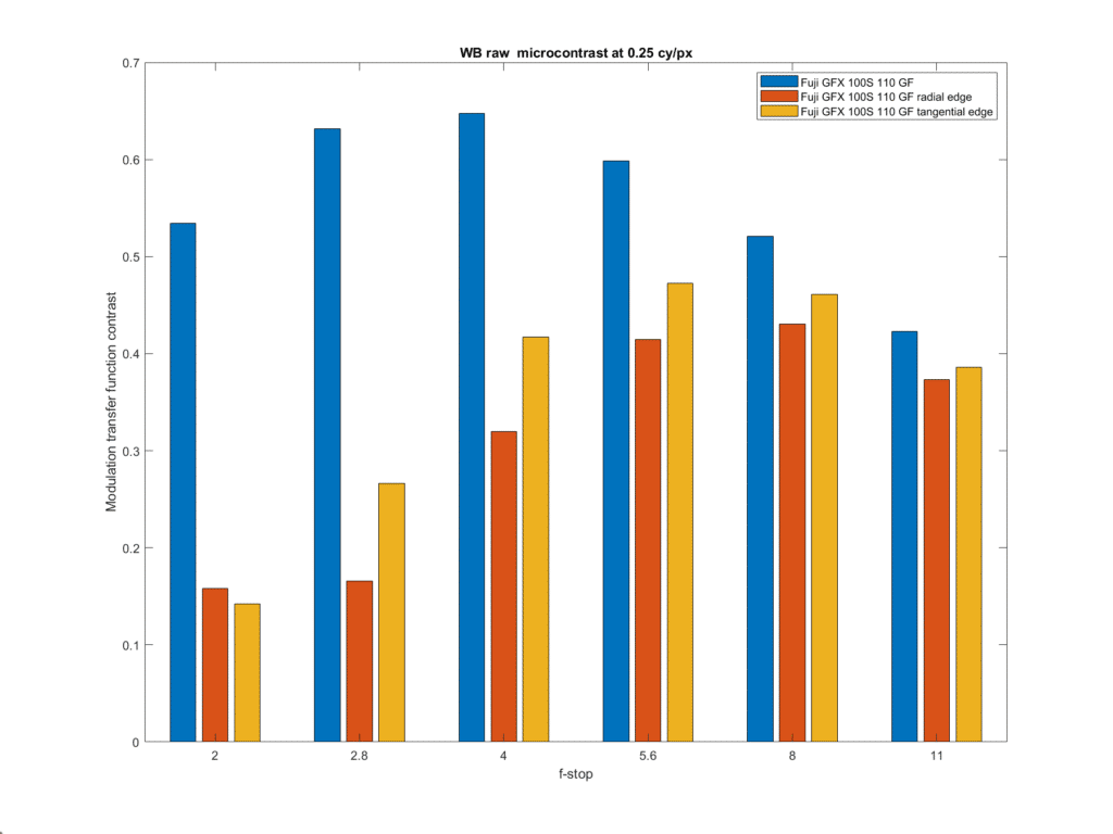
Another way to look at sharpness is microcontrast, which is defined as the contrast at a particular frequency not far from Nyquist. I prefer 0.24 cycles per pixel.
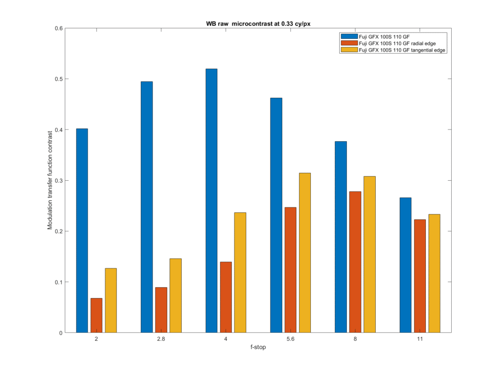
Some people use 0.33 cycles per pixel for microcontrast. At that frequency, there is very little edge contrast when the 110 is opened up.
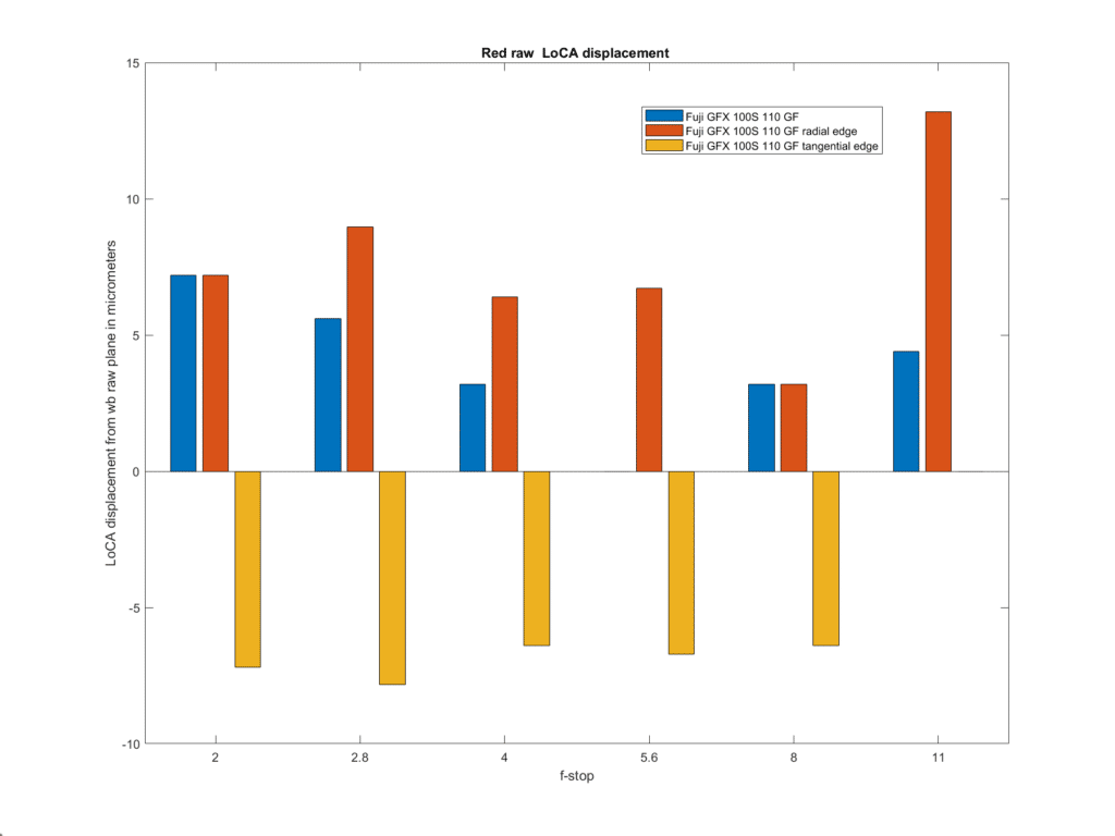
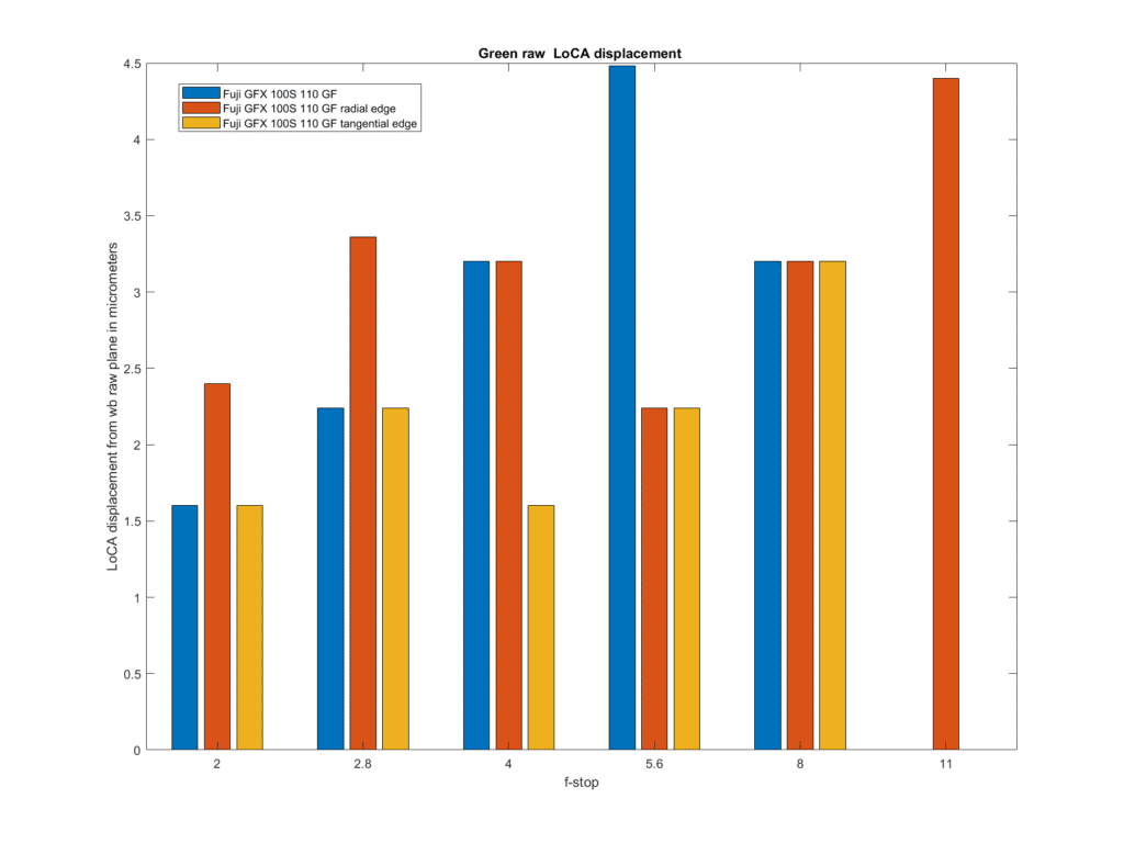
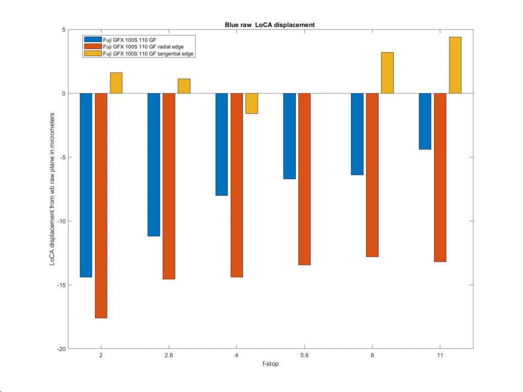
The next think to look at is longitudinal chromatic aberration (LoCA).
What is plotted above is the shift of the red channel with respect to the white-balanced raw. A negative shift is a shift in the direction of being front-focussed. The shifts are not large, indicating that the 110/2 is well corrected for LoCA. It is interesting that the radial edge and tangential edge shifts are in opposite directions.
We wouldn’t expect to see much shift of the green channel with respect to the white balanced one, since the latter is mostly green, and we don’t.
The tangential-edge and radial-edge shift are again quite dissimilar.
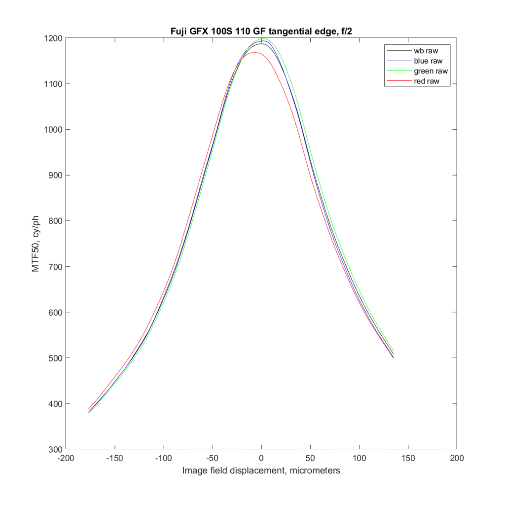
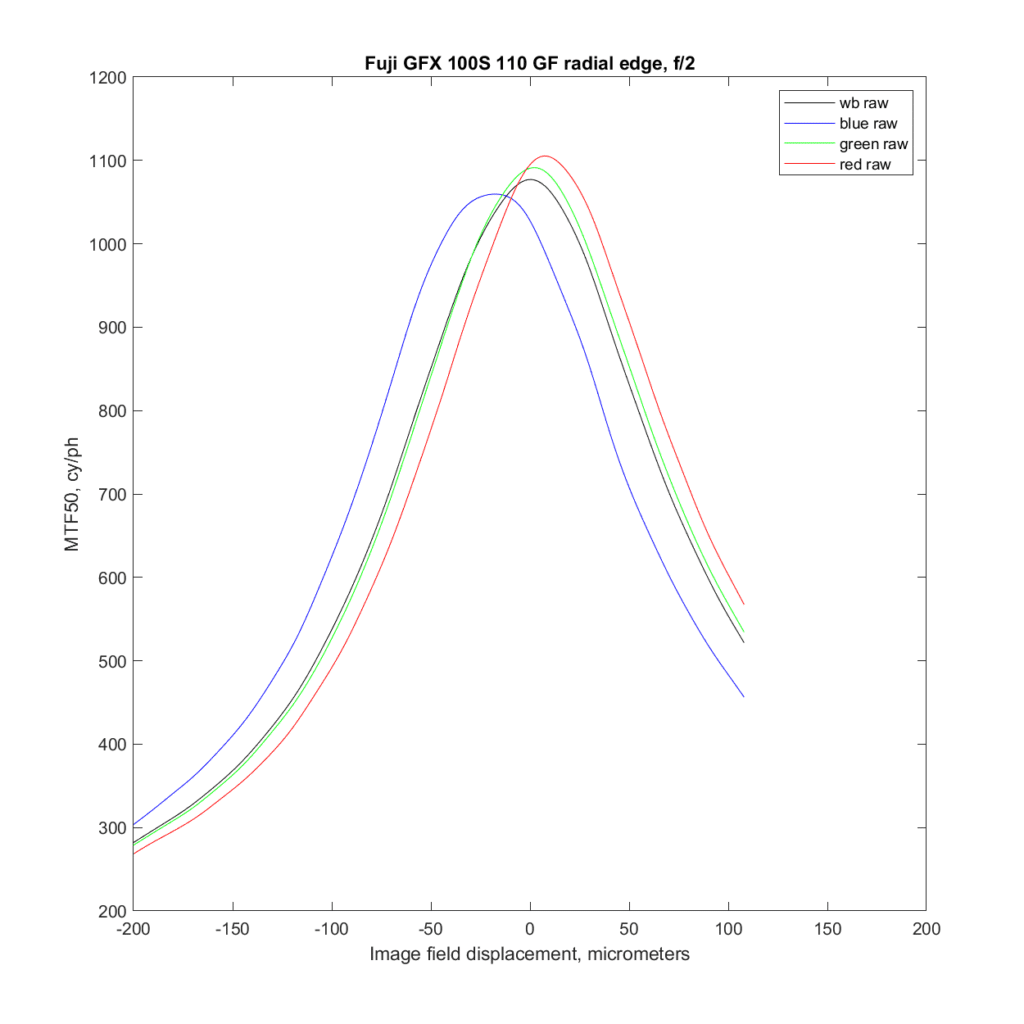
Let’s look at the wide-open transfocal curves.
There is little chromatic aberration here. But look what happens to the radial edge:
Lastly, I’ll show you some transfocal bokeh images.
There are two important aspects to bokeh. It seems most people, when they hear the word, think immediately of the look of parts of the scene that are for out of focus. That’s a good thing to think about when buying, selecting, or using a lens, but the, ahem, focus, of today’s post is going to be on another aspect of bokeh: the characteristics of the lens in reddering subjects that are nearly in focus. The way the lens handles the change from sharply in focus to definitely out of focus is important in the look that the camera and lens give to three-dimensional subjects closer than landscape distances.
The MTF Mapper returns information about the line spread function (LSF), which can be thought of as the radial component of the point spread function (PSF).* The PSF defines the image-forming behavior of the lens. Looking at the PSF yields the same information as looking at the modulation transfer function; the difference is that the PSF is in the space domain, and the MTF is in the frequency domain (thanks to Joseph Fourier, 1768-1830). Sometimes the frequency domain is the way to look at things. Other times, you’re better off staying in the space domain. Trying to assess the rendering qualities of a lens in the space domain seems to work better. For one, it’s pretty easy to do it in a way that allows you to visualize the color effects. For another, due to looking at out of focus distant spectral highlights, we are more or less used to looking at PSFs.
The above image is with the 110/2 wide open, looking at the tangential edge shots. The vertical direction is the shift of the focal plane with respect to the plane of the sensor. Focus distance runs from top to bottom, with front-focused at the top and back-focused at the bottom. The horizontal axis a heavily-magnified view of distance in the sensor plane. The colors are highly approximate; I just assigned the raw channels to their respective sRGB channels.
The above image is the same, but for the radial edge. The increased chromatic aberration is visible. Note also that the plane of sharpest detail is more back-focused that with the tangential edge. This disparity as called astigmatism.
Stopping down to f/2.8 and looking at the tangential edge first:
Now the radial edge:
Again, we have astigmatism.
One more stop:


Now the chromatic aberration is mostly tamed.


Jack Hogan says
Nice! One nit pick about slanting edges more than a few degrees from the axes is that the effect of pixel aperture spreads out (from a sinc aligned with an axis to a sinc squared at 45 degrees from it). The impact is less at MTF50 than further down but it has one nonetheless, making apples to apples comparisons with other slants a bit less immediate .
JimK says
Thanks, Jack. That’s one of the reasons I went for the short edge rather than the corner. The camera can stay level, and the angle of the edge doesn’t have to change. I do have to rotate the target slightly about a straight up and down axis to get it into the rectilinear focal plane, but that’s all.
Ilya Zakharevich says
I’m completely confused. Well, it is “the usual” confusing with what to call “radial” and “tangential” for the targets: should it reflect “the visible geometry” (e.g., the “direction of the edge”) or the ”geometry of spacial frequencies” (which “spacial frequency vectors” are exposed by the target).
It seems that you use the the second interpretation, so you “tangential edge” actually goes through the center (when extended)?
JimK says
I used the direction of the edge. The radial edge, if extended, would go through the center of the frame. Well, not actually the center, because it’s a slanted edge, but close.
Ilya Zakharevich says
Are you sure?!
Note the plots with chromatic aberration on the “radial” edge, and none of the “tangential” one.
JimK says
For the most part, we’re looking at LoCA here, not LaCA. If there were much LaCA, you would see it when the image is in focus. You don’t see it on either edge there.
Jack Hogan says
By extracting the MTF of the individual color planes and then combining the results to estimate a system response we are effectively minimizing lateral CA. Equivalent I think to the MTF system performance one could get after LaCA correction, which most raw converters are able to do relatively well these days. I discussed this clumsily in an article a few years ago (Chromatic Aberrations MTF Mapped, Figure 6).
JimK says
The transfocal LSF images are derived from the three raw color planes, and not combined, so LaCA should show up on them, if present.
Jack Hogan says
Ah I see, well done Jim.