Before moving on to optimum resampling strategies in practice, which is where I’m going with this Epson printer testing, I thought I’d take a look at what happens with the 3880 at 1440/720 dpi resolution and “finest detail” unchecked. I used ABW mode, and the same paper as for the other tests.
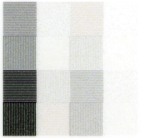
The first thing I did was print out the test grating at 360 ppi:
It looks at lot like it did when I printed it at 2880/1440 dpi with “Finest detail” checked. There appear to be slightly greater luminance-related color shifts.
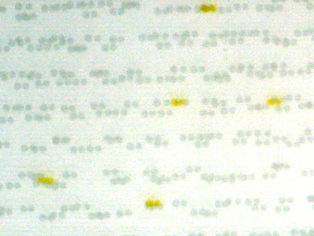
I pulled out the microscope, and here’s what I saw:
This looks about the same as the 2880/1440/FD dpi photomicrographs. The dot size is the same. The typical dot spacing is the same. The minimum sot spacing is greater, but the surprising thing is how little differences that makes in the overall fine structure. You can see the source of the color shifts; this is the same line pitch and gray level printed horizontally and vertically, but, while the only colored ink used in the horizontal pattern is yellow, there is cyan, light cyan, and light magenta in the vertical case.
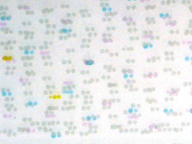
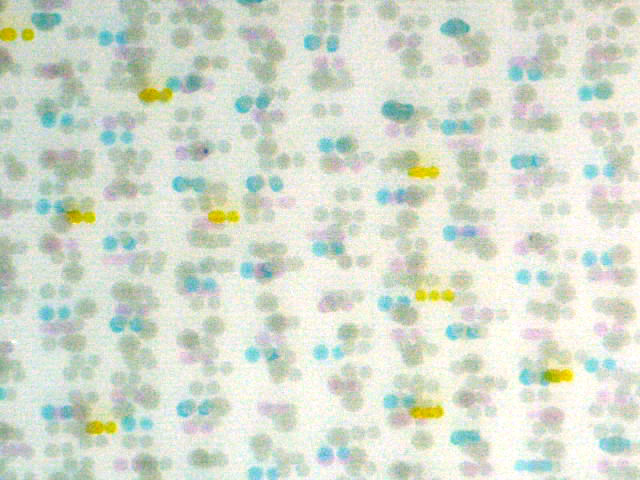
I took a look at a more heavily inked area:
More of same on the dot spacing. You can see a few of the next-larger dots; they appear to have double the diameter of the smallest dots, and somewhat more density.
I moved on to the resampling tests. Here’s what the printer at 1440/720/No FD did when I gave it a 350 ppi grating:
Here’s what Photoshop does when resampling a 350 ppi image to 360 ppi using nearest neighbor:
Conclusion: the resampling rate changes from 720 ppi to 360 ppi when you uncheck the “finest detail” box.
For amusement, I sent the printer a 700 ppi image:
Weird, huh? I resampled a 700 ppi grating in Photoshop, and got this:
Not the same, but not too far off, either.
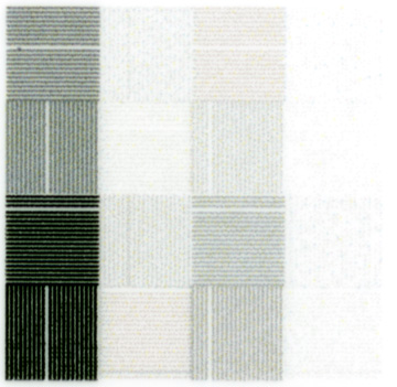
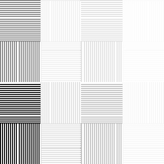
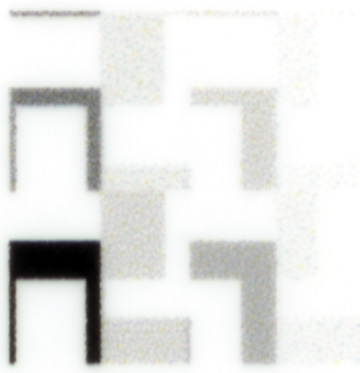

Printers expect a specific ppi….which has nothing to do with the dithering, but everything to do with the driver interpolating the wrong ppi to the one it expects.
Mike Chaney covers this in: http://ddisoftware.com/tech/articles/march-2010-smart-photo-printing/
“…Loss of detail: Printer drivers are designed to do one thing well: place dithered dot patterns on the page. They are not particularly good at preparing the final image to fit/align with those dots, however! Dumping a photo of arbitrary resolution (size) to a specified print size will lead to artifacts such as jaggies or aliasing in the print. This is even true when the original photo has more resolution than your printer since “odd” resolutions (example: 814 PPI) don’t mix well with printers running multiples of either 600 or 720 PPI. Most printer drivers use a very basic form of interpolation such as bilinear interpolation which is not particularly effective at smooth and detailed resizing…”
As you and the reference you cited both say, the printer drivers are rigid about the pixel pitch. I’m not sure why they are built that way, since the error diffusion algorithm doesn’t require that the image be resampled at other than the final dot pitch of the printer. The printer drivers may resample at intermediate pixel pitches such as 360 ppi and 720 ppi to make the diffusion dither computations simpler, but it doesn’t allow the printer to deliver all the resolution of which it is inherently capable, and, as we’ve seen, can create artifacts.
Jim
I suspect you will find that the artfacts are primarily the result of the interpolation….i.e. resampling to the ppi expected by the driver.
You can get best results by doing the sesampling yourself, with a good algorithm. One of the reasons I use Chaney’s Qimage Pro. It will (always) do it for you….plus add smart sharpening based on changes in output size.
We may be in violent agreement on this. I’m saying there are artifacts caused by the driver’s having an intermediate resolution that it expects and resamples to if it doesn’t get. If the driver just applied error diffusion to the input pixels at a resolution equal to the native printer resolution, then one set of artifacts would be eliminated.
Jim
Sorta…
We are both saying that if you do not give the driver what it wants (ppi), you are not going to get the optimal quality out of the printer.
I am not sure exactly what you mean by, “… If the driver just applied error diffusion to the input pixels at a resolution equal to the native printer resolution…” I assume you mean that the resampling, for Epson, would then need to be 1440 ppi or 2880ppi.
If that is what you mean, that would require huge files to be sent to the printers. I believe that the printer mfg. request a subset of that to reduce the file size needs…and that the algorithms they use are optimized to dither based on that input.
Unfortunately, if you do not resample to the ppi required, the driver does not use a very sophisticated interpolation routine. Bicubic, in Photoshop, is not that much more sophisticated, which is why there is a market for resampling/”blowup” software….and then sharpening must be done at this final size (which the printer drivers do not do).
Again, this is why I use Qimage (I’m just a user). It uses very sophisticated interpolation routines, does the sharpening for you, and basis this all based on reading (automatically) the requirememnts from the printer (based on print quality driver settings)….and the size print you define.
So, if I understand you correctly, the model is that the driver sends contone pixels to the printer, and the printer does the diffusion dither. A corrolary of that would be that most of those check boxes on the driver screens are just messages to the printer.
My model was that the driver did the diffusion dither, and sent printer pixels (or dots) to the printer.
You argue that that is impractical based on bandwidth and buffer file size. Lets run some numbers. Sending the contone pixels to the printer would, for 1440/720 dpi settings, result in 8 bits per color plane times 3 color planes times 360 pixels per inch times 360 pixels per inch equals 3.1 million bits per square inch. Or, you could do the color separation in the driver and send 8 bits per color plane times 8 color planes (one for each color ink) times 360 times 360 equals 8.27 million bits per square inch. Having the driver do the diffusion dither function would mean that it had to send 2 bits per printer pixel (dot) (that can handle three dot sizes plus no dot at each dot location) times 8 inks times 1440 dots per inch times 720 dots per inch equals 16.6 million bits per square inch.
From a bandwidth perspective, it seems that all these numbers are feasible; the range over USB 2.0 is from more than 150 square inches per second to 29 square inches a second. These numbers are well beyond the rate that the printer can print.
From a buffer size perspective, even if the driver writes the whole file before letting the printer start, we’re talking about no more than 166 MB for an 8×10, 664 MB for a 16×20, or a bit over 1.2 GB for a 20×30. I use a lot of layers, and regularly have 1.5 GB source files, so those numbers don’t seem scary.
That said, I recognize from the way the driver/printer behaves, that the division of labor between the two is probably as you say. It’s just not the way I’d design things if I ran the zoo.
The advantages of putting all of the screening in the driver would be: better resolution in the print, fewer artifacts, the possibility of third-party drivers with special characteristics, control of the individual ink color planes by the color management system (does anyone else think it’s weird that an Epson printer can’t accept a CMYK data stream?), user (or at least color profile) control of grey component replacement and undercolor removal, sharpening at finer resolutions than the present driver pixels, and blue noise amplitude variation dependent on the amount of detail present in the image (you’d need less blue noise if the image already had a lot of high-frequency content).
I do not think I said all the work was done in the printer. I do not know what pieces are done in the driver or in the printer firmware….and frankly I really do not care. I am sure the guys writing RIPs know, as they are writing their own “drivers”.
For me, I just know there are rules…and all the printer manufacturers seem to follow the same “rules”. That is, there is an expected PPI they expect (based on driver settings). If you do not provide that to them, they will resample the input, so that the follow on routines are working with an expected input and variables do not have to be handled downstream.
If you want optimal quality, you live by the “rules” or accept something less. Depending on the image, you may not notice any difference. In the extreme case you choose, you get significantly worse, most likely due to the interpolation routine the printer software used.
This can be avoided by using a better interpolation routine to get the input in the form the printer expects and will use without change. As I am sure you are aware there are many different interpolation routines and some work better with some images than with others.
In addition, as I said in an earlier post, optimal quality is usually accompanied by sharpening specific to the final resampling….which we do as, for example, one of the last steps in Photoshop. If Photoshop is not the last resampling step, but the printer software is, the sharpening will not be optimal to the final resampling.
As I said, I find it a lot easier to live within the “rules” of the printer mfg. and am very happy with the print output I get. Qimage makes this easy for me. I have never, with current Epson wide body printers, found the need for a RIP. However, to get what you want might require that or require writing your own custom RIP. 🙂
John, we agree that you want to do the resampling yourself, or have a program like the one you’re using do it for you. The image will be resampled during the printing process, and you can either leave that to chance or make sure it’s done right. As a user, that may be all you need to know.
My attitude is different. I’m an engineer. I spent six years working on image processing. I see the way things are and think that they could be a lot better. That’s where I’m coming from when I decry the resampling of the contone image to another contone image at 360 or 720 ppi.
Jim
Other than how we do resampling, I am not sure where we differ.
I just took your 72ppi jpeg (ptg1.jpg) image and printed it on my 3800 in a 5″x5″ square (97ppi). It was printed on Ilford gloss, with a custom icc profile (Spyder3Print w/ grey extensions). The print quality in the driver was set to 1440, which Qimage shows as expecting a 360ppi image. The Qimage interpolation was used was ‘Hybrid’ and smart sharpening set a 5 (default).
It printed out with crisp, tight grids…looking quite similar to the image shown on part #1. Be glad to scan and send to you if you wish.
I am also an engineer…at least by education. I spent 36 years in the computer industry, the last last 20 in PC product management/development…so, while not specifically in printers, I understand the tradeoffs that need to be made, particularly when one needs to support a large variety of operating systems, computer systems, and users.
It maybe cup half full vs half empty, but I see things the way they are and try to make the best with what I am given.
I have only recently found your blog and am really enjoying it and it’s insights and knowledge….thanks…