Note: this post has been revised and corrected based on input from DPRevived and the PS&T forum on DPR. Thanks to all involved.
Recently, I wrote two articles for Lensrentals on raw exposure.
One of the takeaways from the articles was, with modern cameras, by far the biggest win associated with exposure to the right (ETTR) occurs at base ISO. At the same exposure, there is little return in increasing the in-camera ISO setting to push the histogram up against the righthand side. I presented a handwaving argument for that, and a technical one, too. But I sensed that I’m not getting through to everybody. So, I’ve been looking for a better presentation.
Before I dive in, I should mention that Bill Claff has done some good work in this area. Once you learn how to read them, Bill’s curves are very useful. But understanding what’s behind the curves is a bridge too far for some people. First, you have to get your head around how photographic dynamic range (PDR) is calculated. Then, you need to understand the machinations that lead to the shadow improvement curves. If you’re technically sophisticated, it’s not hard. If you have a hard time remembering your high school algebra, it’s tougher.
Let me present what I’ve come up with, and I’ll walk you through it.
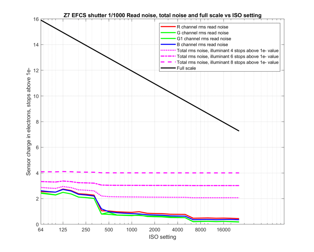
The above set of curves is applicable to a Nikon Z7. Data was obtained by dark-field images with electronic first-curtain shutter (EFCS) at 1/1000th second. The vertical axis is log base 2 of the electron count. If you’re adverse to logarithms, just think of it as sensor response in stops.
This presentation reflects a basic fact about CMOS sensors. There are photodiodes associated with each pixel. The photodiodes react to photons falling on them by producing free electrons. The photodiode response to light, measured in electrons at the photodiode for a given light intensity at the sensor, is unaffected by camera ISO setting, except that higher ISO setting can induce clipping. The graph shows how changing ISO setting affects the upper limit of how much light can be recorded, and how the effective lower noise limit changes as well.
In the above curves, there is no normalization for sensor resolution; Bill’s PDR curves are normalized. The red, green, and blue lines are the read noise referred to the sensor photodiode itself. They can be thought of as the noise floor. You will be able to make out details in the image below that floor, but they will be extremely noisy and, in my opinion, not useful for anything approaching general photography. The opposite end of the dynamic range is captured by the black line. Light levels above that will not be captured at all, but clipped to that value. The engineering dynamic range (EDR) at each ISO setting is the vertical distance between the black line and the red, green, and blue lines.
Take special note of the way the read noise declines at ISO settings above 5000. This is not a welcome occurrence, since it is the result of Nikon’s digital processing of the raw files. I would suggest avoiding those settings unless you have no alternative. However, the reduction in read noise upon transitioning from ISO 320 to ISO 400 is real, and is the result of the dual conversion gain architecture of the Z7 sensor. You can see that the read noise is essentially flat from ISO 64 through ISO 320, and from ISO 400 through ISO 5000. The common term for those regions is “ISOless”. You can see what happens to the EDR as you increase ISO setting in those flat regions: read noise stays about the same, but full scale drops, leaving you with less EDR.
But there’s another kind of noise that affects the shadows in images. It’s called photon noise, or shot noise, and it is an inescapable result of counting photons, which is what the sensor in your camera does. I’ve added curves in magenta that indicate the sum of the photon noise and the read noise for three different signal levels.
The highest signal level is graphed with a dashed line. That signal level can be plotted on the graph as a horizontal line at the vertical axis tick labeled 8. That’s about 8 stops below full scale for ISO 64, and with a conventional exposure where a 100% matte reflective surface is full scale, would correspond to about a 0.4% matte reflective surface, or about 5 stops below middle gray. You can see that the read and photon noise at that signal level is virtually a straight line: ISO setting makes no difference. I probably should have stopped the high signal-level noise curve at ISO 8000, since after that it is above full scale.
The next highest signal level is plotted with alternating dash lengths. That signal level can be plotted as a horizontal line at the vertical axis tick labeled 6. That’s about 10 stops below full scale for ISO 64, which is very dark. You can see some changes in the photon plus read noise line there, but they are trivial compared to the loss in the highlights as you increase the ISO setting.
The lowest signal level is plotted with short dashes. That signal level can be plotted as a horizontal line at the vertical axis tick labeled 4. That’s about 12 stops below full scale for ISO 64, which would correspond to a stygian matte reflective surface. At that level, there is a useful, but small, improvement in dynamic range when increasing the ISO setting from 320 to 400.
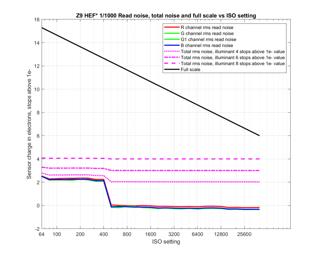
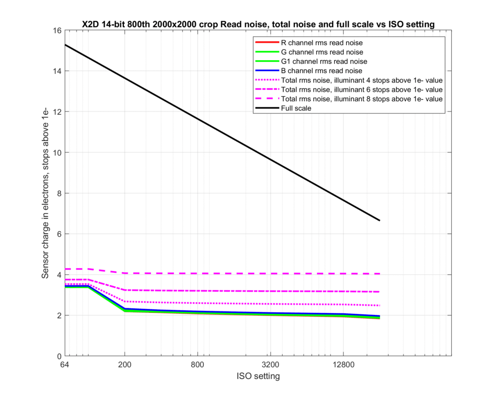
Here are similar curves for two more modern cameras.
Nikon Z9:
Hasselblad X2D-100C:
Except for the transition from ISO 64 to ISO 100, the Hasselblad ISO steps are full stops, which is enough that the change from ISO 100 to ISO 200 offers no improvement in dynamic range even for the lowest signal level plotted in magenta.
What’s the take-home lesson? Increasing ISO setting in-camera decreases headroom much faster than it lowers shadow noise. Be careful when cranking up the ISO.
Caveats (warning, some of these are technical):
This post only applies to raw shooters. The rules are different for in-camera JPEGs.
Some cameras, at some ISO settings, don’t apply gain to the raw signals before writing the data to the raw file. They expect the raw developer to do that. The Fujifilm GFX 50S and GFX 50 R are such cameras, but the GFX 50SII is not such a camera.
Modern CMOS cameras use a combination of methods to apply gain to the charge on the photodiode. One method is to change the size of the capacitor associated with the sensor pixel, so that the same number of electrons results in different voltages at the input to the source follower. Another is to change the gain applied to the signals from the source follower before the analog to digital converter (ADC). This is usually done with a device called a programmable gain amplifier (PGA). A third way to increasing the raw values written to the file is to apply digital multiplication to the output of the ADC. Some cameras use all three of these methods at some ISO settings. The ADC is designed to clip before the voltage at the capacitor associated with the photodiode becomes significantly nonlinear. So all three methods result in the same clipping at full scale shown on the plots above.


Luís Filipe da Cunha says
“Some cameras at some ISO settings, don’t apply gain to the raw signals before writing the data to the raw file. They expect the raw developer to do that. The Fujifilm GFX 50S and GFX 50 R are such cameras, but the GFX 50SII is not such a camera.”
Hi Jim,
does this mean something positive about the GFX50S and 50R?
Is the “gaia” something artificial/negative?
Thanks,
Luís
JimK says
I much prefer the way the GFX 50S and GFX 50R handle the ISO controls to the way the GFX 50S II does it. When you are thoroughly in the ISOless region, amplifying the data before writing the raw file just results in needless chances for clipping the highlights.
Luís Filipe da Cunha says
Thank you very much; got it .-)
Matthew says
Thanks for this Jim.
I just moved fromZ7II to Z8.
Need to rethink use of AutoISO.
Is this a good strategy? If not please recommend.
– If shooting outdoors in generally bright conditions, or in studio with higher power strobes, turn off AutoISO, ETTR at ISO64, and then recover in Lightroom
– If in lower light, indoors, studio with low power strobe, or with longer focal lengths that need faster shutter, the turn off AutoISO, ETTR at 400 (or should it be 500?), and recover in LR?
– In less critical varied shooting, turn on AutoISO at base 64, and deal with less-than-optimal results (but gain the ease of use of AutoISO.)
I wish Nikon would add a feature to AutoISO to “leave at 64, then jump to 400 (or 500?) when needed.
JimK says
That’s the best way to go. I don’t know what you mean by “recover in Lightroom”.
400 it is. But ISO 100 or 200 is better than 400 if you have enough light.
I am not a fan of auto-ISO under any circumstances.
Carsten says
I guess „recover in Lightroom“ means increasing „Exposure“ in Lightroom if the image is underexposed, i.e. too dark, due to not increasing ISO.
Thanks a lot for the illuminating question as well as for the illuminating answer!
Christer Almqvist says
You wrote:”I wish Nikon would add a feature to AutoISO to “leave at 64, then jump to 400 (or 500?) when needed.”
Yes, you are right; that would be very practical. Why has it not been implemented years ago? Probably because considered too basic by the programmers who like to include esoteric video features not needed, at least not by photographers.
Personally, I wish Sony would add a feature to AutoISO called “ISO-less” with an initial setting of 100, but increased to 640 when the selected minimum shutter speed would no longer be achieved.
Barry says
640 is Sonys most noisy ISO from my experience…I wish Sony would eliminate ISO 640 from the camera period.
JimK says
Which Sony camera?
Garry says
Jim I always love reading your posts and your DPReview commentary. Unlike you, I’m more of a user of other peoples’ thoughts 😉 🙂
As a Canon user, eg EOS M and EOS M3, I have written Lua scripts, under CHDK and Magic Lantern, to give me an in camera auto ETTR feature, albeit using data from the camera’s viewport, ie not a pure RAW, full resolution ETTR, but better than guessing.
Looking at the Photons to Photos data I’m always looking to assess when I can claim my Canon camera has become ‘ISOless’. That is, as I increase ISO from the base ISO, my Canons can not be said to be behaving in an ISO manner, but I believe I will get to an ISO value, say, 1600, but camera specific, when after this, the camera is behaving like an ISOless camera.
I appreciate one needs to be careful with pattern noise etc, ie one may need to increase ISO to get on the right side of this.
So my question is this. Do you have any guidance, using the PTP charts to arrive at a pragmatic understanding of when a camera can be said to be behaving in a (near) ISOless manner, ie above this ISO value there is no point in increasing ISO (ignoring shutter speed needs)
Cheers
Garry
JimK says
“Do you have any guidance, using the PTP charts to arrive at a pragmatic understanding of when a camera can be said to be behaving in a (near) ISOless manner, ie above this ISO value there is no point in increasing ISO (ignoring shutter speed needs)”
Look at Bill’s input-referred read noise charts. When they flatten is where the camera becomes ISOless.
Garry says
Cheers
John Moyer says
Your last paragraph is your best explanation yet. Thanks for that.
John
Paul says
“The ADC is designed to clip before the voltage at the capacitor associated with the photodiode becomes significantly nonlinear. ”
If it weren’t, what would the non-linearity look like? Would it be similar to the compression we see the shoulder of film’s sensitometric curve?
JimK says
Yes.
Carsten says
I think I got the main statement of this post, but I do not really understand your curves. What does the y-axis show in which physical unit?
I read „sensor charge in electrons“ as „sensor charge in the number of electrons“, but what does „stops above 1e-“ mean then? Is 0 (zero) the charge of one electron and 16 the charge of 17 electrons. This does not seem to make sense for me – and isn‘t related to stops.
JimK says
You got the part about counting electrons right. Here’s the stops part. One electron is 0 stops above one electron. Two electrons is 1 stop above one electron. Four electrons is 2 stops above one electron. Eight electrons is 3 stops above one electron. One stop is a doubling of the number of electrons. Another way to look at it is that the vertical axis is log base two of the number of electrons.
Carsten says
„log base two of the number of electrons“ – that makes sense!
Stops is a logarithmic scale, that was clear to me, but I still didn’t come up with this simple connection. I guess what threw me off was that zero is not zero, but one electron.
But please don’t change, otherwise someone else might not be able to translate the logarithmic scale to stops.
Bruce says
Jim, I really want to thank you for this look behind ISOless/ISO invariant portions of the sensor. That said, I’m a relatively new photographer, and much of what you’ve discussed in detail here is above my knowledge base or understanding. A few questions: 1. Without going back for an EE education, is there a blog/location that breaks all this down to the ground, and slowly ramps up the terminology so that a novice at this can follow along and become educated? 2, In the simplest description, I thought ISO was analog amplification of signal AFTER exposure – amount of photons/light, reached the sensor – via aperture and shutter speed. In a portion of your blog, you note that increasing ISO can affect the upper limits of how much light can be recorded. I was under the impression (perhaps incorrectly) that increasing ISO did not make the sensor more sensitive to light – so my question is – where in the process does this amplification above the ceiling or full bucket occur (in lay terms?). 3. From my novice perspective, it appears that the read-noise (front end) is relatively flat from ISO 64 to 480ish, and then drops at ISO 500 (what is going on here? Turned off capacitor?), and then flat again making 64 to 480 ISOless and 500 and above ISO-less as well – with the penalty being possible blown highlights and reduced DR. Is there any real benefit to obtaining appropriate exposure using shutter speed and aperture, and then raising ISO from 400 in the Nikon Z9 to 500, with the reduction in read noise – if the intent is to raise detail in the shadows, or does the amount of shot noise off-set this (I know it probably depends on the scene). The reason I ask, is that a landscape photographer was making a point that his shadows looked better at higher ISOs with more detail and less noise. Turns out – with my little insight – I asked him if he were using an ISO variant camera like the Canon R5 – and he said he was. I wish I understood most of what I’m talking about here – but I just know enough to be dangerous – and I want to get better are reasoning this out for myself. Thanks for the help.
JimK says
See if this helps:
https://www.lensrentals.com/blog/2023/05/how-digital-cameras-determine-exposure-part-1/
https://www.lensrentals.com/blog/2023/05/how-to-expose-raw-files-part-2/
Bruce says
Thank you, kindly, for the links – and within the links introducing me to Richard Feynman and elucidating the “Rules of the Game”. I will get back to you if I have further questions, but in the meantime, I am very appreciative.
Bruce says
1st: Thank you for the links. I realize they were listed at the top of this post, but I do appreciate the referral. 2nd: I found them very helpful, and of course they raise more questions for me to pursue. Thank you. 3rd: A well known Canon “Explorer of Light” mentioned that he occasionally would bracket ISO when he desired more data push around in post (without the image breaking down). He said the engineers at Canon would look at him funny. That said, given the lower read noise, and improved information in the shadows of certain cameras with dual gain capacitance, might this make some sense (on the Nikon Z9 with ISO 500 on the high end)? Again, thank you for entertaining my novice perspective.
JimK says
I don’t believe in bracketing ISO.
Here’s a Z example, though not with the Z9:
https://blog.kasson.com/nikon-z6-7/nikon-z7-exposure-strategy-an-example/