There have been a few requests for an explanation of the noise floor simulation in the previous post. Here it is.
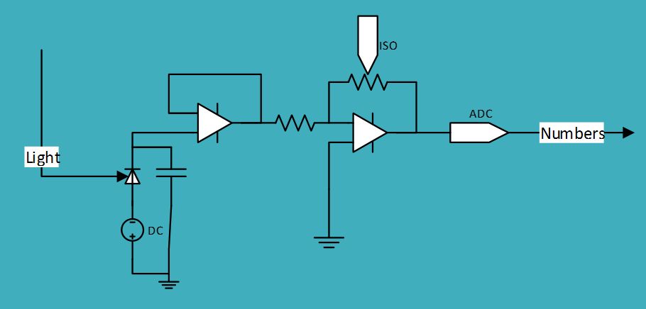
The program uses a model of a digital camera that’s illustrated below in one-pixel form:
Light falls on the back-biased photodiode causing electrons to be released. The electrons charge the capacitor. The buffer amp keeps the electrons from leaking away. There’s another amplifier before the analog-to-digital converter (ADC) whose gain is controlled by the ISO setting of the camera. The ADC converts the output of that amp to a number that’s stored in the raw file.
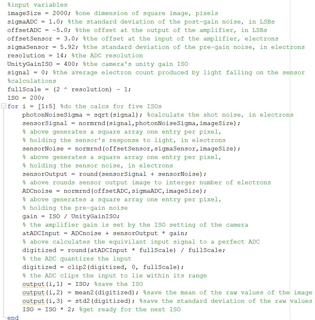
Here’s a heavily-commented version of the noise floor simulator that models a 2000×2000 pixel monochrome camera. A monochrome camera is sufficient, since, in the absence of light falling on the sensor, the color filter array plays no role.


Leave a Reply