I’m going to be needing out of focus (OOF) point spread functions (PSFs) from various lenses for my bokeh simulator project. Here’s how to capture them, for which I am indebted to Professor Hank on DPR. All credit to him.
You’ll need a dark room — thankfully, not a darkroom, just a room that’s dark. Ideally, you want to get at least 50 times the focal length of the lens you’re testing away from the target — more on that in a sec — and, within reason, the farther away you can get, the better.
You’ll probably want a tripod, although it’s not strictly necessary.
And you’ll need a small LED flashlight; the smaller the better. The ones that operate from a single AAA cell are good. The ones that use just one AAAA cell are harder to find, but probably better. If the flashlight has power settings, set it to the dimmest setting. It’s easy to get one that’s too bright, and I’ve never found one that’s too dim.
- Put the flashlight at the far end of the room facing the camera.
- Turn the flashlight on.
- Go back to the camera
- Turn it on, too.
- Douse the lights
- Set the camera’s ISO knob to base ISO.
- Open the lens all the way.
- Focus it to as close as it will focus.
- Center the out of focus image of the flashlight.
- If you’ve got a mirrorless camera, adjust your shutter speed until the zebras go away and/or the right side of the histogram comes off the end.
- For other cameras, take pictures and adjust the shutter speed until that happens.
- Is the blurry disk all within the frame? If so, you’re done. If not, adjust the focus until there’s a fair amount of black around it.
Send me the raw file.
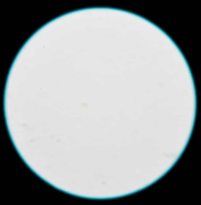
Here is a sample image. It has been cropped, because the OOF flashlight didn’t come anywhere near filling the frame.
Occasionally, you may see a strip across the image. If that happens, take pictures until you get lucky and don’t see it It’s just the flashlight pulsing the LED at high frequencies. If you can’t get it to go away, send me several images with the strip in different places.
Brandon Dube says
This is only going to give you the OOF PSF when the defocus is so extreme that it is >>>>> the aberration contribution to the image, and only on the optical axis though that is a different point.
It helps illustrate / measure axial color (the fringes on the edge) but you’re not going to see much else – – it’s going to be a disk unless the aperture is not circular or is apodized, etc.
Relatively close to being in focus the aberrations will come into play, which is where the interesting things happen.
JimK says
I understand the limitations, but it seems to me that the areas in the image that people comment on wrt bokeh are the greatly OOF ones. Your point about the on-axis nature of the sim is well taken. I don’t know of a simple way to fix that with actual OOF PSFs, but I could imagine doing more with computed ones.
I appreciate your input in this.
Jim
Brandon Dube says
I did a few quick simulations for a 135mm f/2.8 @ 500nm —
first, just defocus : http://imgur.com/a/62pvm
I didn’t convert the units of waves of OPD to image plane defocus or “circ() diameter” since that isn’t really the point here.
Second, with a blend of spherical, coma, astigmatism, and defocus. http://imgur.com/a/UlwDS
I apologize — imgur does not want to order the images properly.
The concentric rings are a sort of interference pattern due to the monochromaticity of the simulation. If you did the whole visible band, they would disappear and you would get a uniform disk.
The X,Y axes are in microns — you can convert to # of pixels for any pixel pitch at will. To go much bigger than this would require a lot of points sampled in the pupil plane, which requires both lots of memory and lots of patience.
Here’s the code: (~3s runtime without the figure saving)
http://imgur.com/a/0ggyW
My instinct is that by the aberrations are significant to around 25-50um blur radius, after which you may as well only think about the defocus.
JimK says
This is great, Brandon. I really appreciate your doing this. So far, the smallest blur circle I’ve been using is 50 pixel diameter (25 pixel radius) on a 2000×1500 image scaled down from approximately an 8000×6000 5-6 um pixel pitch capture. The scaled pitch would be about 20 um, so my 25-pixel radius would be about 500 um. Looks like I could make that almost an order of magnitude smaller if there were a reason to do so. Now I have more confidence in the sim than I did before.
Brandon Dube says
The aberrations aren’t orthogonal as Seidels, but they are as Zernikes. In that framework, you can think of them like any other linear systems component. Noise in cameras is a good analogy, you have shot, bias, and read/dark noise.
You can think of the shot noise as the aberrations, and the read/dark noise as defocus. if your read noise is big, you can’t observe the effects of the shot noise. Likewise, if your OPD from defocus is 2-3x larger than the aberration contribution, you can pretty much ignore it.
The aberration influence is what builds up “bokeh transition zone” effects, which are often the subject of much ado when people discuss lens quality. Beyond the transition zone, axial color, vignetting, the number of blades, and stray light are +- the sole determinants of bokeh.
Jack Hogan says
Would covering the flshlight LED with tin foil and poking a hole through the center with a pin help?
JimK says
That could work.