Cooling a CMOS sensor reduces noise. But which noise? By how much? And is it worth the effort for your application?
Let’s break it down by examining what cooling affects — and what it doesn’t — in the readout chain.
What Do We Mean by “Read Noise”?
Read noise includes all non-random and random noise components that arise after charge generation in the pinned photodiode. It generally comprises:
- Reset (kTC) noise from the floating diffusion,
- Source follower transistor noise (thermal and flicker),
- PGA and analog circuit noise,
- ADC quantization and comparator noise,
- Pattern noise from gain mismatch or bias drift.
A subset of these are affected by temperature.
Cooling Helps
- Thermal (Johnson-Nyquist) Noise
- Generated in resistive elements (e.g., source followers, bias paths).
- Proportional to √T (square root of absolute temperature).
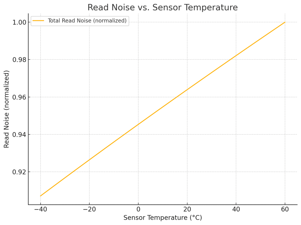
- Cooling the sensor by 20–30°C can lower thermal noise noticeably.
- Flicker (1/f) Noise in Analog Circuits
- Cooling may reduce the low-frequency tail of 1/f noise.
- Benefit depends on circuit topology and process.
- Dark Current Shot Noise
- Not strictly read noise, but cooling helps tremendously here.
- Dark current halves roughly every 5–7°C drop.
- This is vital for long exposures: it reduces both signal bias and noise variance.
Cooling Doesn’t Affect
- Reset (kTC) Noise
- Fixed by circuit design (e.g., correlated double sampling or active reset).
- Not significantly affected by temperature once CDS is applied.
- ADC Quantization Noise
- Determined by bit depth and architecture.
- Unrelated to temperature.
- Fixed Pattern Noise from Mismatched Gain/Offsets
- Usually calibration-related.
- Can shift slightly with temperature but doesn’t scale predictably with cooling.
- Correlated Noise in Digital or Mixed-Signal Paths
- Often due to imperfect layout or shielding.
- Cooling doesn’t help and may actually destabilize bias points in marginal designs.
Cooling Might Affect
- Bias drift in poorly stabilized analog circuits.
- Reference voltage fluctuation in older or consumer-grade sensors.
- Clock-induced charge or leakage paths (varies by process).
In some sensors, these secondary effects can cause temperature-dependent noise “surprises,” but they aren’t predictable and aren’t the primary target of cooling.
How Much Improvement Can You Expect?
| Cooling ΔT | Typical Read Noise Reduction |
| 0°C to –20°C | ~10–25% (thermal/flicker) |
| 0°C to –40°C | ~20–40% in best cases |
| >–50°C | Diminishing returns for read noise; dark current keeps falling |
In practice, dark current noise drops faster than read noise, and is usually the dominant justification for heavy cooling — especially in long-exposure imaging.
| Aspect | Cooling Helps? | Notes |
| Thermal noise | ✅ | Minor but real benefit |
| Dark current | ✅✅✅ | Major benefit, especially long exposures |
| ADC/Quantization | ❌ | No effect |
| Fixed pattern noise | ❌ | Calibration-dependent |
| kTC reset noise | ❌ | Removed via CDS |
| Flicker noise | ⚠️ | Slightly improved in analog domains |
Conclusion
Cooling a CMOS sensor helps — but mainly where physics and thermodynamics allow it. It won’t magically erase all read noise, and it won’t affect digital quantization artifacts. But when dark current or analog thermal noise are significant, cooling is one of the most effective tools in your imaging toolbox. Tt’s not a cure-all, but a well-targeted upgrade for low-light imaging.
Leave a Reply