There has been a little interest in developing a protocol for slanted edge modulation transfer function (MTF) testing that is sufficiently standardized and reproducible that the results from various amateur practitioners can be compared fairly.
There are several things that conspire to make slanted edge MTF testing irreproducible:
- Alignment errors
- Field curvature
- Target differences
- Lighting differences
- Focus errors
In this post, I’ll propose ways to deal with each of these things, based upon the backlit razor blade methods that I’ve developed for testing macro lenses on-axis. In all cases, I’ll trade off time and the number of exposures for repeatability and reproducibility. The idea is that this protocol might be useful for a single person testing her own lenses, not an operation like Lens Rentals, where time is money.
I’ll assume you have a MTF testing program like Imatest or MTF Mapper, and you know how to use it. If not, feel free to read on, but when you’re finished with this post, you won’t have everything you need to go and do the measuring.
Alignment errors can be dealt with by making the slanted edge subtend only an angle in the field of view big enough for accurate MTF calculations. This means only a few edges per exposure. For now, let’s think in terms of one or two.
Field curvature can be handled, if the edges are compact, by focusing on the area in the field containing the edges, no matter where in the frame that happens to be.
Target differences can — I hope — be handled by using a readily available double edged razor blade as the target. I have no way to print a target that is anywhere near as sharp as using a backlit double-edged stainless steel razor blade. When I print targets, the numbers that I get are affected by the file contrast, the print size, the paper finish, the printer, and the camera distance. The razor blade is so sharp that camera distance is a non-issue, and none of the other variables apply.
I have not used the Imatest photographic transparencies with their light box, one because they are so small and two because they are expensive and, I believe, beyond what most of my readership is willing to spend to test lenses.
Lighting differences will be taken care of with readily-reproducible illumination that is non-critical.
Focus errors will be managed by using multiple exposures and a focusing rail. Ugh, right? Yeah, I know, that’s a PITA, but I know of no other way to find the point of peak focus reliably. I’ve given up manually focusing when accuracy is primary. I use a motorized rail for focus bracketing. I can’t get repeatable results any other way. Making lemonade out of lemons, we’ll use the rail to get longitudinal chromatic aberration ( LoCA) and focus shift data at the same time.
The test revolves around a razor blade.
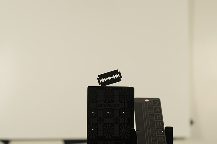
The blade is stuck into a block of wood, which is mounted to a tripod with a gear head that I can use for alignment. Any way to get the blade perpendicular to the lens axis will work, and the alignment is not critical. Behind the razor blade is a white piece of paper illuminated by two light sources. I use Westcott 5000K LED panels. When you turn the room lights off and the panels on, here’s what you see with a Sony a7RII, a 90mm lens and the target at 2 meters:
The above image was made with the camera set to APS-C mode, which crops the full frame image. I use this more when doing on-axis testing to save disk space and processing time. For on-axis testing, I use the framing lines in the Sony camera to put the center of the edge right smack dab on-axis, like you see here.
With the Sony a7RII, the combination of 90mm and 2 meters gives a usable target extend of about 250 pixels. You want the extent small, so that alignment is non-critical. You want it big, so that the slanted edge testing is more accurate. This seems like a good compromise. For other focal lengths, you can use the formula:
distance = 20 * focal length
where distance and focal length have the same units, say, millimeters. Yes, yes, I know; the constant should be 22.2, but I rounded. If you’re testing an APS-C 24 MP camera, you can get a little further away. If you’re testing a 24 MP full frame camera, you need to get a little closer.
You’ll note that, with a 200mm lens, you’ll want to be about 4 meters away. If that strains the size of the room you’re in it will be fine if you’re closer, since the razor blade is so sharp.
With a short lens like a 20mm, you’ll want to be about 40 cm away. You won’t be able to back up from that a lot and still have enough pixels covering the blade.
The blade angle should be somewhere between 3 and 14 degrees. Actually, if you avoid certain critical angles, it can be almost anything.
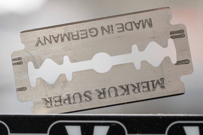
Here’s the razor blade front lit:
I don’t think it makes much difference what brand you buy, but, in case it does, you now know the brand I use.
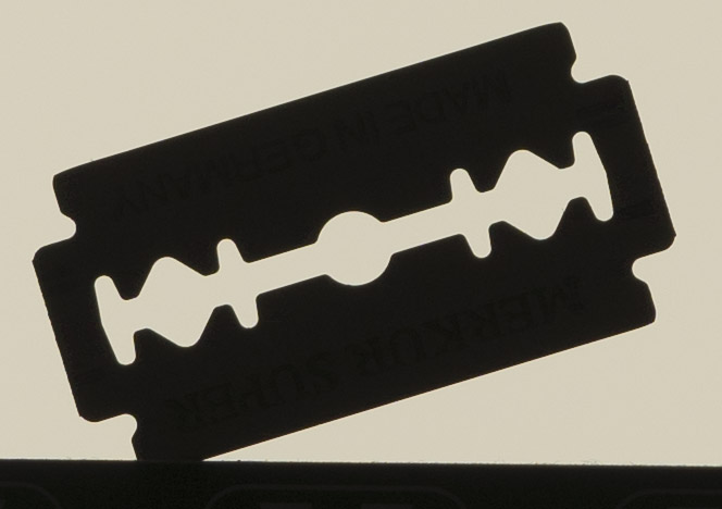
Here’s a close up of the blade when it’s back lit:
I use a Cognisys computer-controlled focusing rail with 200 mm of travel. In order to make sure that I don’t run into the stops, I only use 190mm of that. I focus in the middle, back the rail to the far from target end, and make a series of images spanning 190mm.
How many images?
For the macro work I made 200 exposures. That took about 10 minutes. For the work I’ll show you today, I made 50 images at each aperture. That turned out to be about as few as I think I could get away with, although, if you aren’t aiming for the whole LoCA/focus shift/peak MTF50 package, you might be able to get away with fewer.
Could you use a manual focusing rail? I think you could, but it would get to be a pain after a while, unless you just wanted peak MTF for each f-stop, in which case you could focus at that f-stop and focus bracket four or five shots on either side of that.
I used the Sony 90mm f/2.8 macro as my test lens.
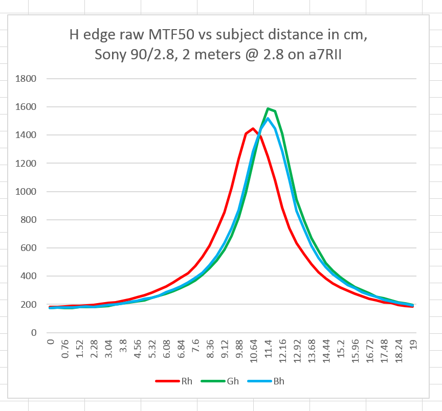
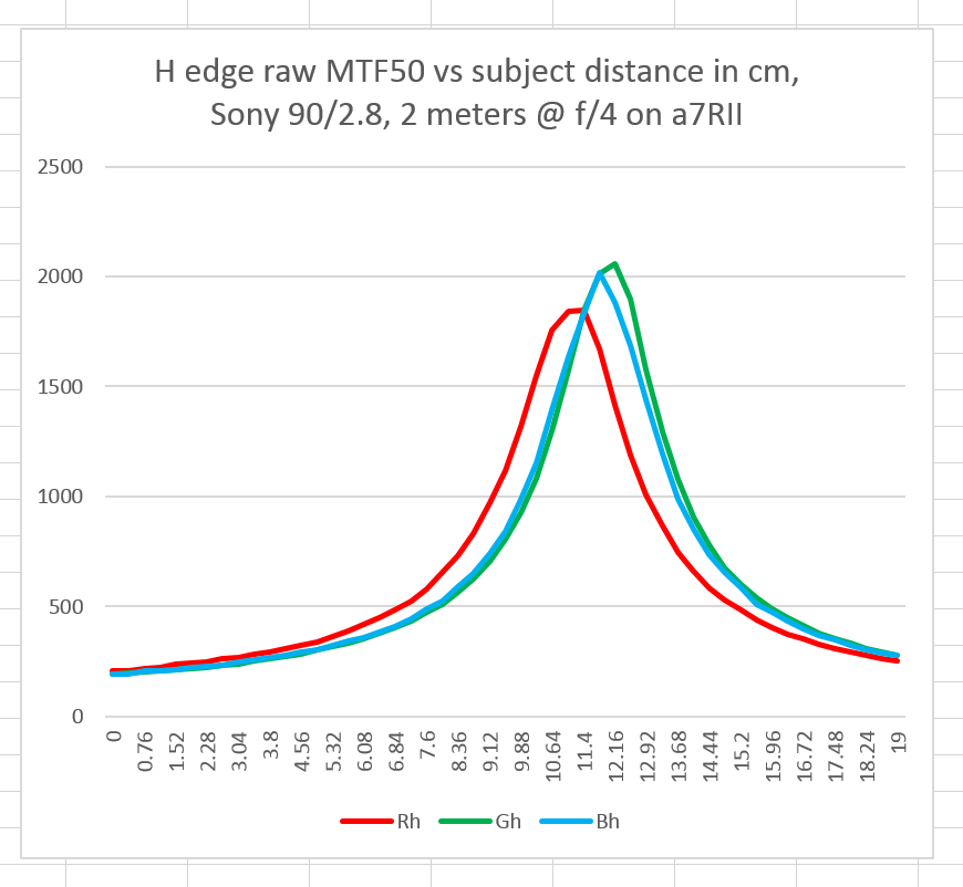
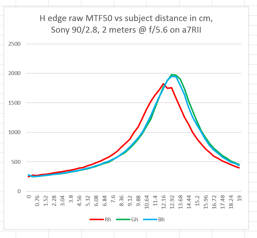
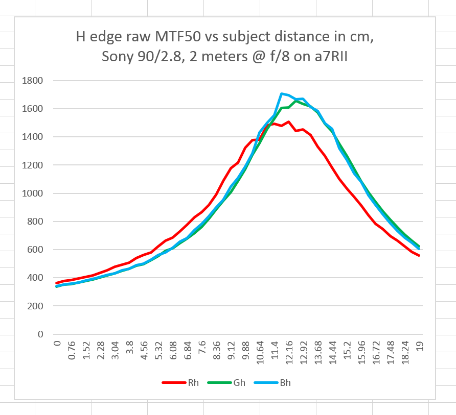
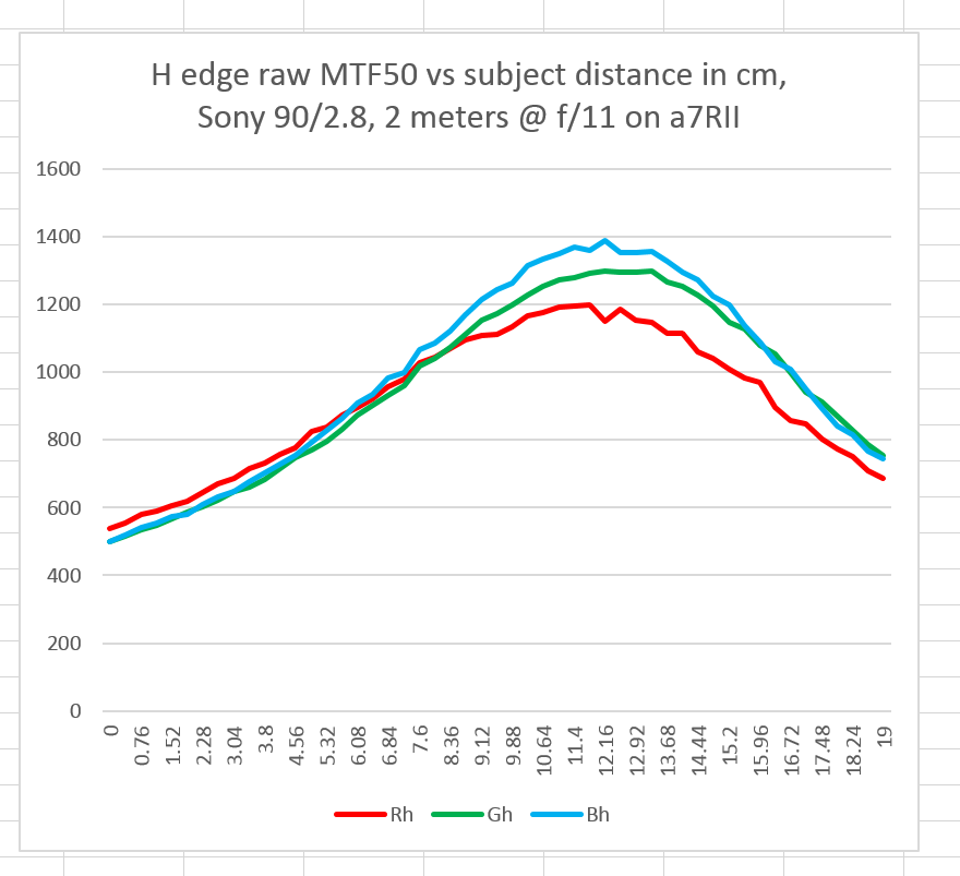
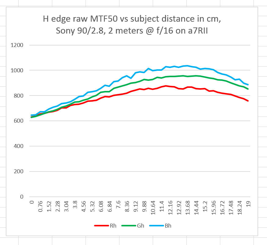
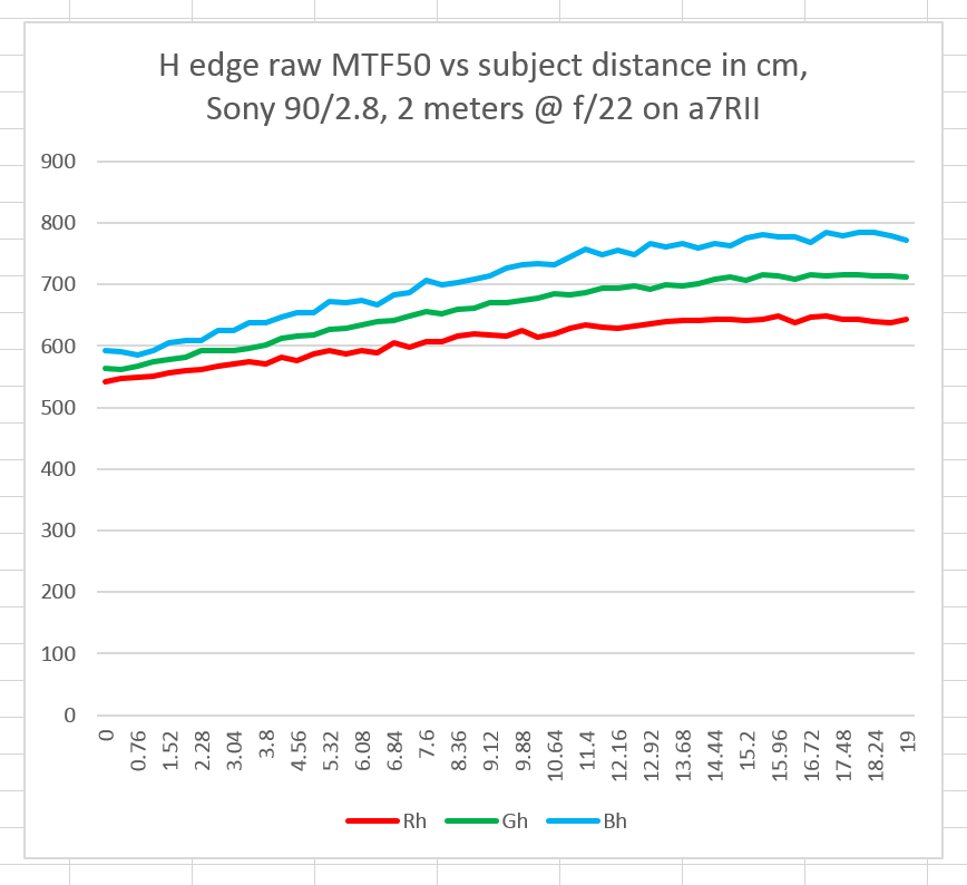
I developed the files in DCRAW, and analyzed them for MTF50 in each raw channel using MTF Mapper. In MTF Mapper, I used a 150×150 pixel region of interest (ROI), even though I could have used a bigger one, do make sure the razor blade was large enough in the target for useful data. Here are the LoCA results for each whole f-stop:
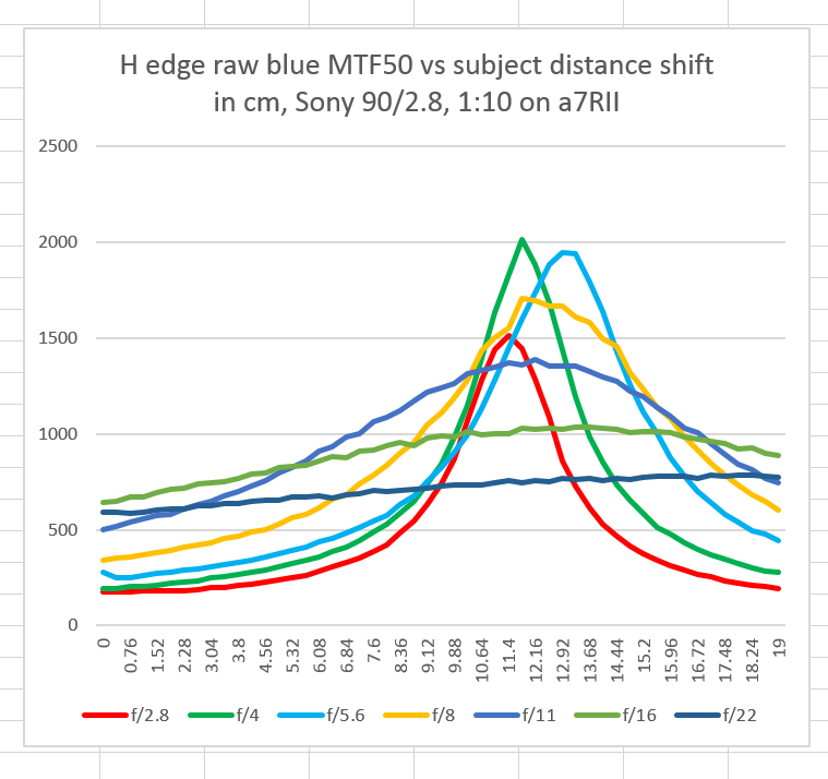
Distance is the horizontal axis, with the left hand size having the subject farther from the camera than the right hand side (The camera moves closer to the subject by 3.8 mm after each exposure). The vertical axis is MTF50, measured in cycles per picture height, assuming the entire sensor is used.
It is pretty obvious that the green and blue raw channels focus in the same place, and the red channel focuses farther away.
As the aperture is closed down, the depth of field swamps out the LoCA.
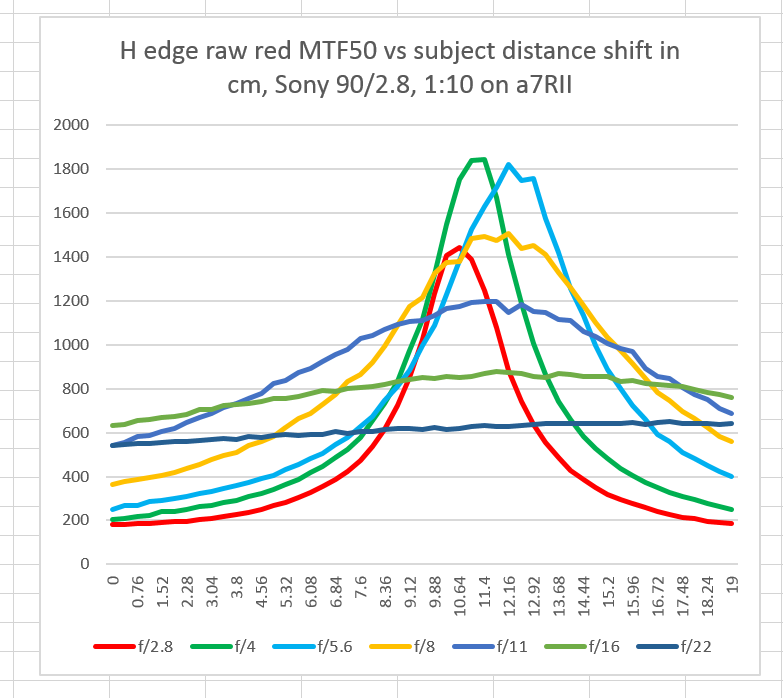
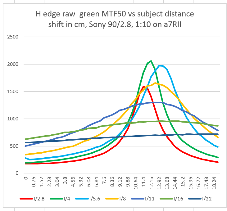
Plotting all apertures and each of the raw channels on its own chart give us focus shift information:
You can see that I probably missed the peak of the f/5.6 curve, indicating that 50 exposures is marginal.
Ub this one, I probably missed the peak of the f/4 curve.
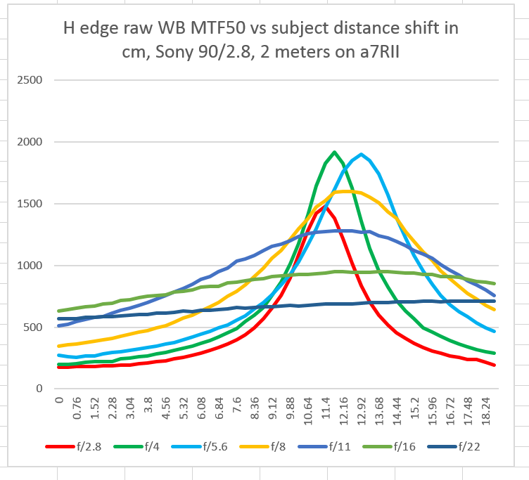
A white balanced set of curves uses all the raw channels:
Because there’s more data, the curves look smoother, but the f/4 one is still suspiciously pointy on top.
Where shall I go with this? I’m open for suggestions.
How do you know the target contrast? MTF50 is 50% of what?
50% of the low frequency modulation, as measured by the slanted edge analysis program.
Isn’t that affected by the overall contrast of the lens though, if you don’t have an absolute brightness difference measurement? This is probably giving them a boost versus the actual MTF50…
Jim,
Thanks for your interest and time spent thinking this through.
“subtend”? I’d never heard this word, and checking Wiki didn’t clear up anything. Arcs? In Lynn-speak and not Jim-speak, does that mean the razor IS NOT square to the plane of the sensor, so it’s silhouette is more like a trapezoid?
“if the edges are compact” ???
I have about 20 questions like that, and checking Wiki doesn’t necessarily clarify things for this engineering grad from 40+ years ago.
Would this $625 Cognsis rail be appropriate?
http://www.bhphotovideo.com/c/search?Ntt=motor+focus+rail&N=0&InitialSearch=yes&sts=ma&Top+Nav-Search=
I’m not clear what a “geared tripod”. My impression is that it is more than tripod legs with a crank that controls the height of the center rail, but maybe that’s it. Or are you referring to the head itself that is geared, like an Arca-Swiss C1?
http://www.bhphotovideo.com/c/search?Ntt=geared+tripod+head+arca-swiss&N=0&InitialSearch=yes&sts=ma&Top+Nav-Search=
The angle subtended by the extant of the razor is the angle of a line drawn from the lens entrance node to one side of the razor to a line drawn from the other side of the razor to the other side of the razor. The smaller tha angle, the less critical alignment is.
Then they subtend a small angle.
Jim
Does this mean that the razor blade being “square” to the camera sensor is less critical? Is it actually preferred to be a bit non-square?
I’m fuzzy by what you mean by “on-axis testing”.
These razor blades? I’m relieved they aren’t $10 each.
https://www.fendrihan.com/products/10-merkur-double-edge-safety-razor-blades
Alignment error, in the case of the razor blade, means that the angle between the plane defined by the flat part of the blade and the lens axis is not 90 degrees.
You want that angle as close to 90 degrees as possible, but eyeball aligning appears to be good enough.
Jim
Testing with the target in the center of the frame is on-axis testing. The target is on the lens axis.
Those are the blades I use.
I like this controller better:
https://www.cognisys-inc.com/store/stackshot3x-ex-rail-pkg.html
Jim
Looks like LensRentals has a focus rail available with computer driven motor.
https://www.lensrentals.com/rent/support/tripods-monopods/tripod-heads/cognisys-stackshot-3x-macro-rail-package
When you use the rails, do you start with the camera in the middle of the movement at sharpest focus you can get manually, then use most of the rail movement so it starts off way off focus in one way, and then way off focus the other way, in 2mm steps.
I am surprised it takes 190mm (7.5″) with a 90mm lens with a target 2 meters away to make sure you capture the best focus. I suppose the FE55 lens would be ok less rail movement.
I focus in the middle, back the rail away from the target to near the end, and make a series of 50 (actually, 51; it’s a fencepost issue) over 190mm, for 3.8mm per step.
I’m not trying to just capture the best focus position. I want to look at all the curves in the presence of LoCA and focus shift. I can’t refocus at each aperture, either, that would mess up the focus shift measurements.
I don’t think I used the word geared in this post. In any event, I use a geared head to align the target, but you can you any head you please.
Jim
Whew.
BTW, I’ve noticed that even in my basement with a “floating slab” floor, walking around the room induces more vibration that I would expect. You can see this movement more obviously with magnified live view. If a truck drives by, it moves. Also a car, but less so.
That makes me inclined to keep IBIS on even when using a tripod, but that may be incorrect.
I use an Arca-Swiss geared tripod head under the rail. You can use whatever you want.
Jim
To avoid need for a computer-driven motorized rail, would it be feasible to use a 20″x30″ white foam board on a partially open door?
This foam board would have a bunch of cheap double-edge razor blades carefully attached with thick, double-sided tape. These might be much sharper substitutes for the printed trapezoids in a previous blog article … seven shot
http://blog.kasson.com/?p=14942
http://www.walmart.com/ip/Personna-100-Pack-Double-Edge-Stainless-Steel-Safety-Razor-Blades/33449586
That might work well, but I think it would be harder to make it reproducible.
Is your goal to do lens testing for your own amusement, or is it to be able to compare your numbers with those of others?
Jim
I’m just “throwing out ideas” from “the peanut gallery” that might or might not cause someone else who knows what they are doing … such as yourself … to react with something like …
“Hmmmm … that obviously won’t work, but with these [fill-in-the-blank] changes, it might be Kaizen (there’s always room for continuous improvement). ”
I’ve noticed what might be part of that with the idea of using glass instead of foam board.
Here’s some speculations… at some point, the proposed MMUG (or whatever name it gets, if any) calls for a “show of hands” of how many are willing to proceed at an “out of pocket expense t” of some range of costs, such as:
$250, $500, $1000, $2000, etc.
aka “put your money where your mouth is” ?
It might be that more than a couple would proceed at $500, and almost no one at $2000 … just to use made up numbers.
Suppose the “sweet spot” is $1000?
Perhaps you + a few others work out a BOM (bill of materials) near $1000 that had some reasonable likelihood of working with a motivated geek who has over-the-top attention to detail and suitable “fiscal throw-weight”.
That might be the “pay to play”, assuming they also had prerequisites that might include an a7Rii + FE55.
If there were a large number of people willing to proceed, it might be possible to work out something so that the synthesized “razor blades on glass (not foam board)” could be done in some bulk way and sold to the participants at less than they could do it themselves. Dream on?
Further speculation:
If this MMUG actually happens, it wouldn’t surprise me if someone has serious 3D printing skills and experience. They might come up with something that someone like myself with access to a 3D printer (local library) could duplicate with a reasonably high level of precision and uniformity.
Using the perhaps flawed “blades on glass” as an example, it might be Kaizen’ed so that the 3D member[s] could publish the “formula / plans / recipe” for mounting the glass and blades in a uniform, consistent way.
Or not?
WRt budget, my objectives are to some up with something that would be pretty cheap at a basic level — say, less than $200 in gear that a well-equipped photographer wouldn’t already have. After that, there would be things that could add convenience and accuracy: rails, sophisticated lighting, tools, etc. At this point, I think the knowledge of usage of some slanted edge program has to be assumed, as well as skill with some spreadsheet program, and possibly some programming skills for automating data crunching.
But, to be frank, the only person seriously interested at this point appears to be you, so maybe it’s too early for a poll.
Jim
Hi Lynn,
Just keep in mind that if you use multiple razor blades, then it is critical to keep all of them in the same plane. I have found that MTF Mapper picks up warping in a standard 80 g/sqm paper printed target, even though the bumps in the paper are barely visible to the naked eye.
The tricky part is ensuring sufficient contrast: if you stick the razor blades to an opaque backing (foam board or steel plate), you will not be able to use silhouette lighting. The razor blades are not uniform enough to allow any front lighting.
I might try some some experiments with a razor blade glued to a sheet of glass (since this should be both rigid, and quite flat) — I worry a bit that the glass might interfere with the edge, but some rigorous testing should be able to rule that out.
How critical is lighting? You mention what you use, but without indicating whether a possible MMUG should use the same setup for consistency.
Would bounce flash from a reasonably powerful flash be adequate? Direct flash better or worse?
Bounce flash from the ceiling would have its “flash shadow” beneath the top edge of the razor, which seems good.
I’m going to be testing that in the next few days.
I’m looking forward to that. I don’t have the prerequisites to comprehend much of what you write. That’s not your problem, obviously.
For some of your articles, you are teaching at the 501 class level, and I got a B 40+ years ago on the 101 class related to that topic. Mea culpa.
I find it difficult to sort out what is descriptive rather than prescriptive.
As to background on slanted edge testing, I suggest spending some time on the Imatest web site. They have lots of material there, and pointers to other places.
http://www.imatest.com/docs/
WRT prescriptive vs descriptive, it’s hard for me to tell without more testing of protocol variants. I’m working on that.
Jim
Jim I wonder if I can ask some advice.
I’ve been meaning to get a cognisys rail and controller for a while.
Principally it would be for macro. So the shorter one would be fine.
OTOH the longer one would make it easier to use with many lenses using your testing protocol, which I’d quite like to try (though macro stacking is my main interest, to get more systematic captures than I can manage on my Novoflex manual rail)
I wonder if the longer rail would be a problem for macro work: at very least you’d often be at the very front end of it. Is that an issue, do you happen to know?
As long as there’s room behind the camera for 100 mm of rail to stick out, then you ought to be able to make any images with a 200mmrail that you could make with a 100mm rail.
How about moving the target on a rail, not the camera?
(A razor blade is way more easy to move 🙂
That’s a good idea for heavy lenses and should really help off-axis testing. Thanks! I’ll be exploring this in the future.
Jim
An interesting data point is the f/22 peak at about 710 lp/ph in the G channel. It is significant because at that f/stop diffraction dominates overwhelmingly pixel aperture and axial aberrations (CA+SA) in the center of the FOV.
Theoretical diffraction from a circular aperture occurs at an MTF50 of 0.404/lambdaN. If we assume weighted average lambda of 0.535um in the green channel that would result in a MTF50 of 824 lp/ph, so your measurement is about 14% lower than what theory predicts. In practice there is some residual influence from SA+CA, so the difference is probably a bit lower than that. It would be fun to hunt the rest of it down.
Based on your experience with the Coastal Optical the first thing to check would be how accurate the f-number of this lens is. Jack
Nice analysis, Jack. I’ll run a check on the aperture setting accuracy.
Jim
Hi Jim,
I know it has been years since you posted this entry, but thank you so very much!
As someone attempting to learn the mechanics and mathematics of lens testing I find the content invaluable. Your ability to distill complex subjects and present them in simple terms is amazing.
You mention the testing distance should be 20x (or 22.2) the focal length. Can I ask the significance of that factor?
I’m not particularly interested in the details of the derivation (or the physics behind) the factor. I would just like to gain an appreciation for why 20x is the magic number.
From my DSLR days of fine tuning focus adjustments, I recall that 20x was the preferred test distance. Perhaps it is a coincidence? Back then no one could explain why 20x was important.
My guess is that it has something to do with the angle at which light hits the front element. But I can’t fathom why 22.2 would be optimal (or maybe minimal).
Sorry to pester you with a such trivial question. But, you seem to be someone who would know the answer and might present an understandable response to someone who struggles with physics.
Kind regards,
Warren
20x is a rule of thumb. I’m most cases the lens performance won’t change much from there to infinity. Optical benches typically test with collimated light, which simulates testing at infinity. But if you’re not using an optical bench thr size of the target gets very large a great distance. 20x is a compromise.
Of coarse, lenses that will be used at very short distance should be tested at about that distance.
Got it. Thanks!!!!