This is a continuation in a series of posts on power consumption in the Sony a7RII. The more recent incarnation of the series starts here.
I reported on my battery current measurement setup here. In the last few days, I’ve refined it somewhat, and I’d like to document what I’m doing here, because my techniques is settling down, and I will probably be using it in the future. It seems to have application well beyond figuring out how to maximize the a7RII battery life. Looking at the details of the current flow from the camera battery to the camera itself provides a window into the internal operations of the camera that has revealed interesting details and can serve as the basis for future tests. For example, I can now accurately measure the time the camera takes to acquire focus in autofocus mode under various conditions.
I should warn you all that understanding what I’m doing from the iamges that I’m about to show you requires an elementary knowledge of electronics and electrical circuits. If that is not in your background, maybe you should accept my results on faith (or not) and move on to the next post.
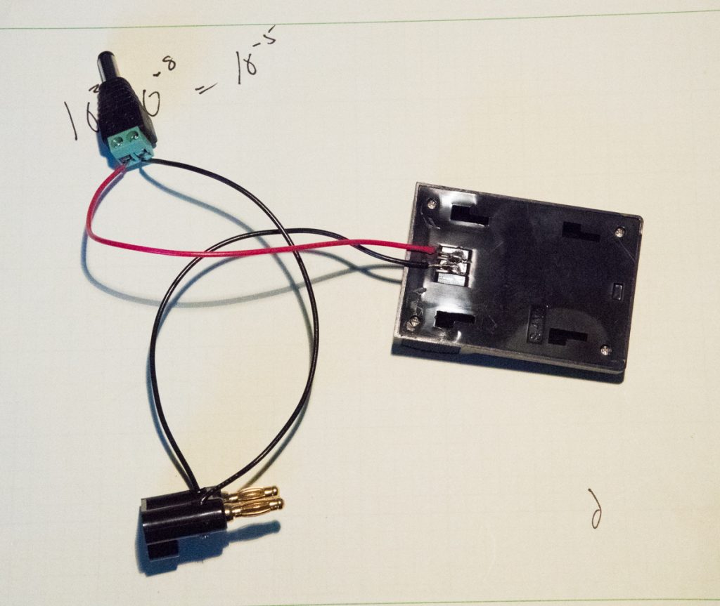
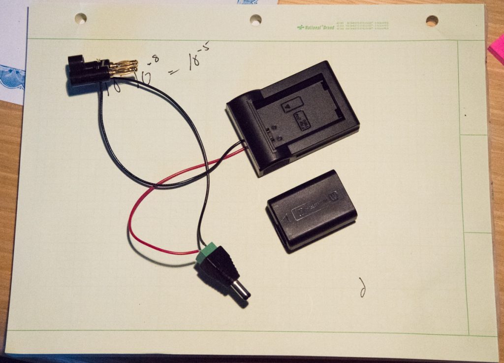
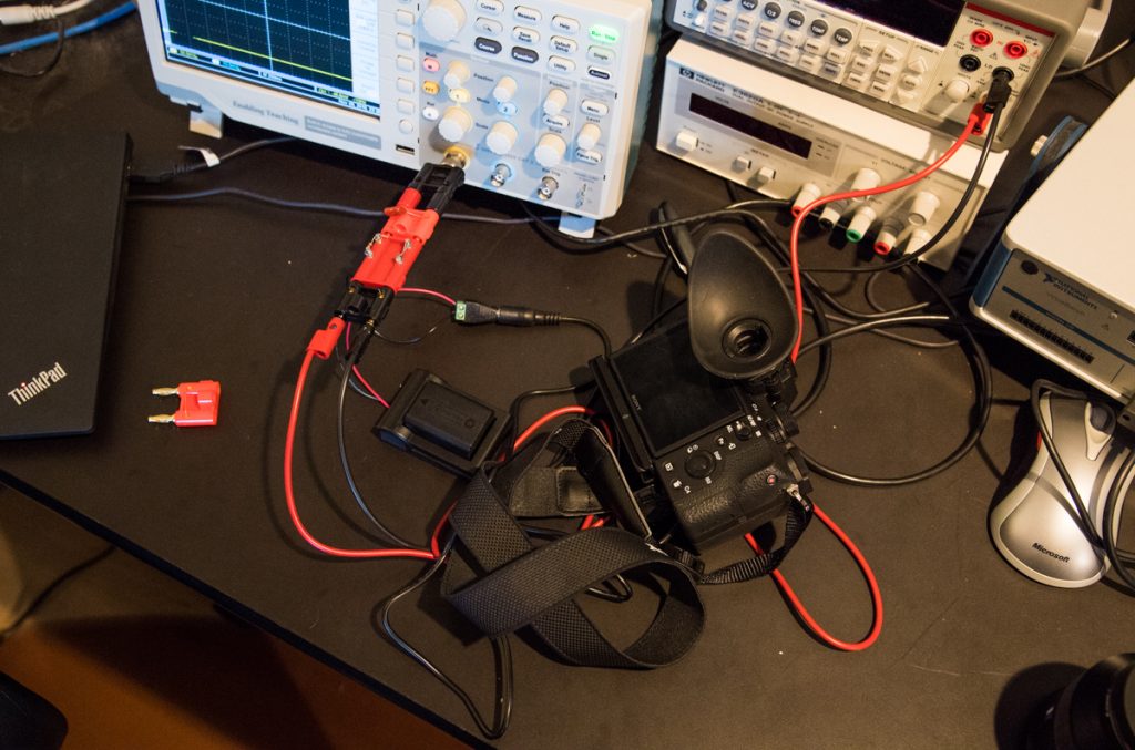
Here’s the first thing that is new. I’ve taken a Wasabi battery charger, and ripped off the battery holder and soldered a couple of wires to it. I’ve run the (red) wire from the positive terminal to an adapter that plugs into the battery replacement of an as power supply for the a7x cameras. I’ve taken the (black) wire from the negative battery terminal and run it to a GR (3/4 inch double banana) plug. The other side of that plug goes to the negative terminal of the adapter and thence to the camera:
Turning the Wasabi part over, you can see the side of it that may be familiar to you:
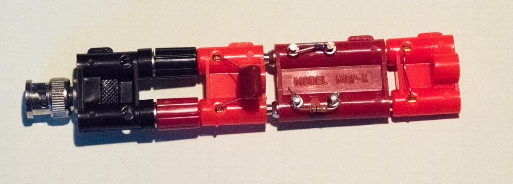
I’ve also revised the part that plugs into the GR plug the you can see above. The stack now looks like this:
Proceeding from right to left, we have a 0.1 ohm nichrome wire shunt, a 1 K ohm resistor in series with the high side of the shunt, a 0.01 microfarad capacitor to provide a 10 microsecond lowpass filter, and finally a GR-to-BNC adapter. The BNC end of the adapter plugs into the oscilloscope. The tabs on the GR plugs indicate the ground side.
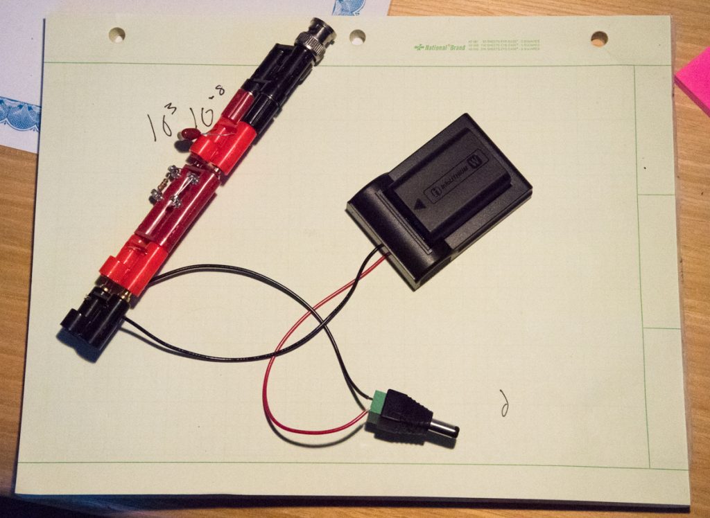
Put the parts together and we have an assembly that looks like this:
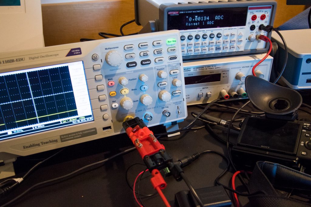
Moving over to the bench where the testing occurs:
We see the camera on the right, the scope on the left, and the Keithley 2100 digital multimeter (DMM) that I use for accurate, but slow, current measurements. In this setup, the DMM provides the shunt resistance, so the 0.1 ohm nichrome shunt is not used.
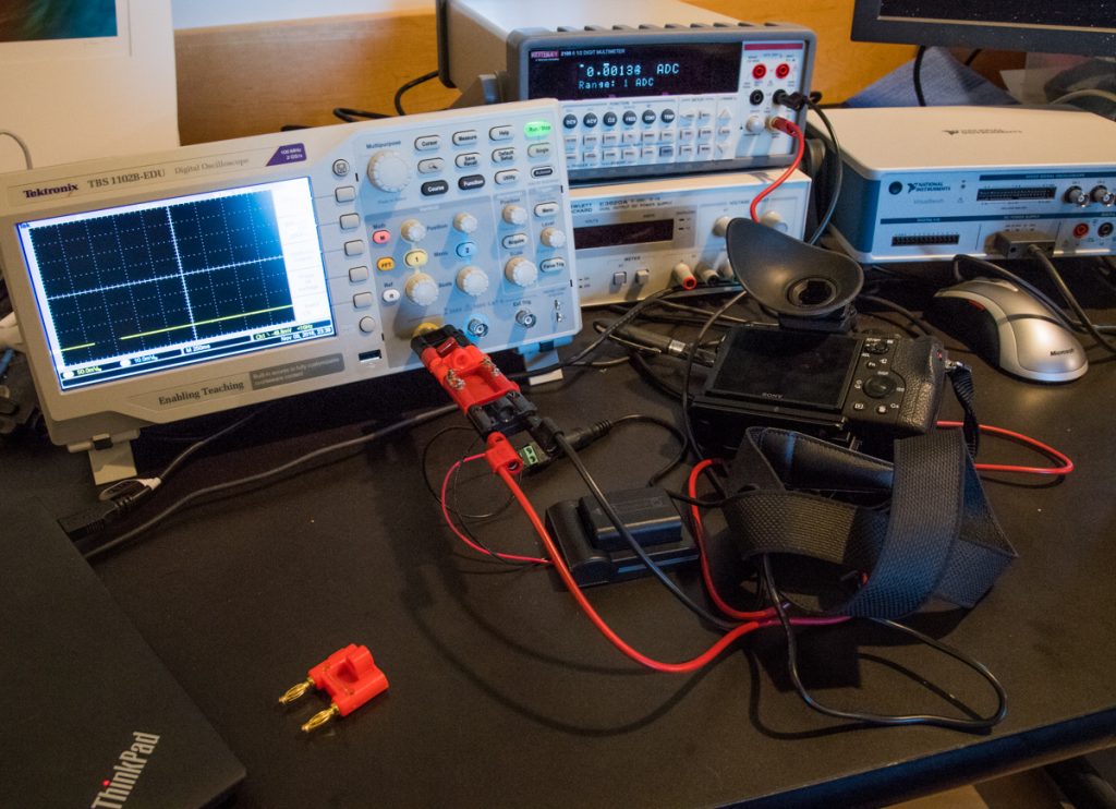
If we back up a bit, it looks like this:
You can see a bit of the computer used to capture the data on the lower left, with the unused 0.1 ohm shunt next to it. The DMM is sitting on an hp power supply, which I used with a somewhat different collection of hardware when I don’t want to use an actual battery. I don’t do this much, because the power supply is only rated to deliver one amp, and, with the shutter in operation, the camera draws more than that. I may throw a big capacitor across the power supply terminals in the future, but for now I’m using the real battery. All of the things I’ve shown you so far have been done using the real battery.
Leave a Reply