This might turn out to be just one more hopeless “there’s something wrong on the Internet, and I must fix it” posts, but maybe it can rise above that. I’ll do my best.
In a DPR forum, there is a thread about 4-shot pixel shifting. Under that protocol, which is available on Bayer color filter array (CFA) cameras from Sony, Nikon, Fuji, and others, the IBIS (or sometimes other devices, but IBIS is the current most popular method) makes four shots sequentially. One shot is made with the sensor in the normal position, one shot with it shifted horizontally one pixel, one shot with it shifted vertically one pixel, and one shot with it shifted horizontally and vertically one pixel. This gives four images in which each pixel position is exposed through each of the four raw channels. Thus, enough information is recorded in the 4-shot sequence so that no demosaicing is necessary to achieve a full-color image. In postproduction, the four shots are assembled into a developed RGB image. Since there is information for each of the four raw channels at each pixel location, no interpolation or other demosaicing trickery is needed.
Four-shot pixel shift virtually eliminates false-color aliasing artifacts, but does not eliminate luminance aliasing. Proof? I while back, I made four-shot pixel shift images with a Fuji GFX camera under tha following conditions:
- 110 mm f/2 lens on the GFX 100S
- f/4
- C1 head
- RRS legs
- Sinusoidal Siemens star
- Slanted edge above it
- Electronic shutter
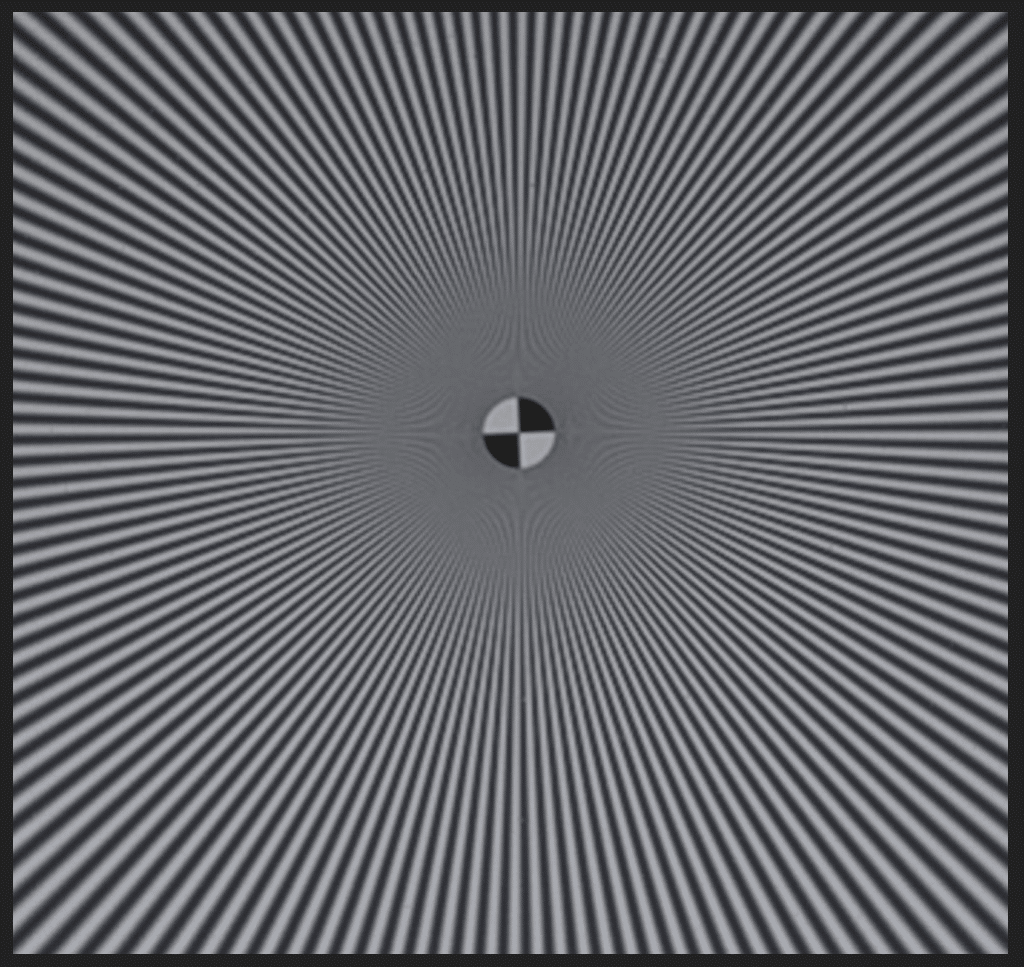
Here are the results, developed in Lightroom:
As you can see, the false-color aliasing artifacts that you’d normally get are not present, but there is definite lumiance aliasing.
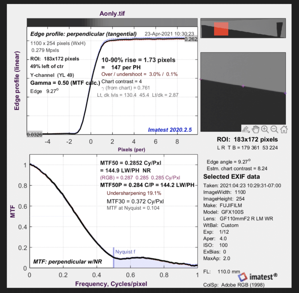
Looking at the modulation transfer function gives a quantitative appreciation for that.
The aliasing is not huge; the MTF above Nyquist is around 10%. But it’s enough to visually affect the Siemens Star image.
With that as background, let’s look a a few quotes from DPR that bothered me. I’ll number them for reference later.
- Using pixel shift to capture high-frequency details and then adding a low-pass (AA) filter is counterintuitive.
- Also, the low-pass filtering by the AA filter will impact the precise alignment required for pixel shift.
- Hence, combining pixel-shift with AA is a no-go.
4….pixel shift… reduces aliasing and hence eliminating the need for AA.
5. In fact, the presence of AA becomes redundant and actually counterproductive when using pixel shift as it will interfere with the effectiveness of pixel shift.
A reader pushed back on the last point above:
My understanding of AA filters is that they are part of a sensor assembly and moves with it – so how is the alignment of the AA filter with the photocells affected?
And the answer was:
6. It’s about the precise alignment of projected/sampled image, not the sensor/AA.
7. Once the projected image passed through AA filter, the boundaries are no longer precise.
8. If you believe my explanations are incorrect, let me hear why no camera manufacturers have produced a camera with both pixel shift and a hardware AA filter.
In hopes of raising this post above mere whining that somebody posted something somewhere that’s not right, I will try to delineate the errors in the above.
Because something is counterintuitive (1) doesn’t make it wrong.
Basing a conclusion on an erroneous assumption. Four-shot pixel shift doesn’t eliminate aliasing, and therefore aliasing can be improved in four-shot pixel shift images if an anti-aliasing (AA) filter is used.
Conflating blur and alignment. (2, 6, 7)
Correlation does not imply causality. (8).
Before I get to a point for point refutation of the above, let me for background explain how AA filters (aka optical lowpass filters or OLPFs) in modern cameras work.
The most common AA filter is a 4-way Lithium Niobate beam-splitting anti-aliasing (AA) filter. Here’s an explanation of how those work.
Here’s a relevant quote:
A slice of Lithium Niobate crystal, cut at a specific angle, presents a different index of refraction depending on the polarization of the incident light. Let us assume that a beam of horizontally polarized light passes through straight, for the sake of the argument. Vertically polarized light, on the other hand, refracts (bends) as it enters the crystal, effectively taking a longer path through the crystal. As the vertically polarized light leaves the crystal, it refracts again to form a beam parallel to the horizontally polarized beam, but displaced sideways by a distance dependent on the thickness of the crystal.
Using a single layer of Lithium Niobate crystal, you can split a single beam into two parallel beams separated by a distance d, which is typically chosen to match the pixel pitch of the sensor. Since this happens for all beams, the image leaving the OLPF is the sum (average) of the incoming image and a shifted version of itself, translated by exactly one pixel pitch.
If you stack two of of these filters, with the second one rotated through 90 degrees, you effectively split a beam into four, forming a square with sides equal to the pixel pitch (but often slightly less than the pitch, to improve resolution). A circular polariser is usually inserted between the two Lithium Niobate layers to “reset” the polarisation of the light before it enters the second Niobate layer.
Here’s a post on a similar subject that I made a few years ago. I’ll hit the high spots here. If you want details, click on the link to the left.
If a pixel were a true point sampler, it would have a point spread function like that below:
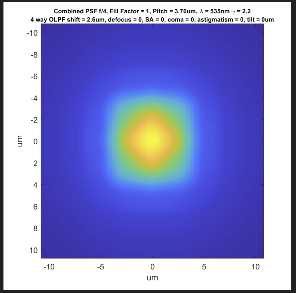
Adding a 4-spot AA filter would yield this PSF:
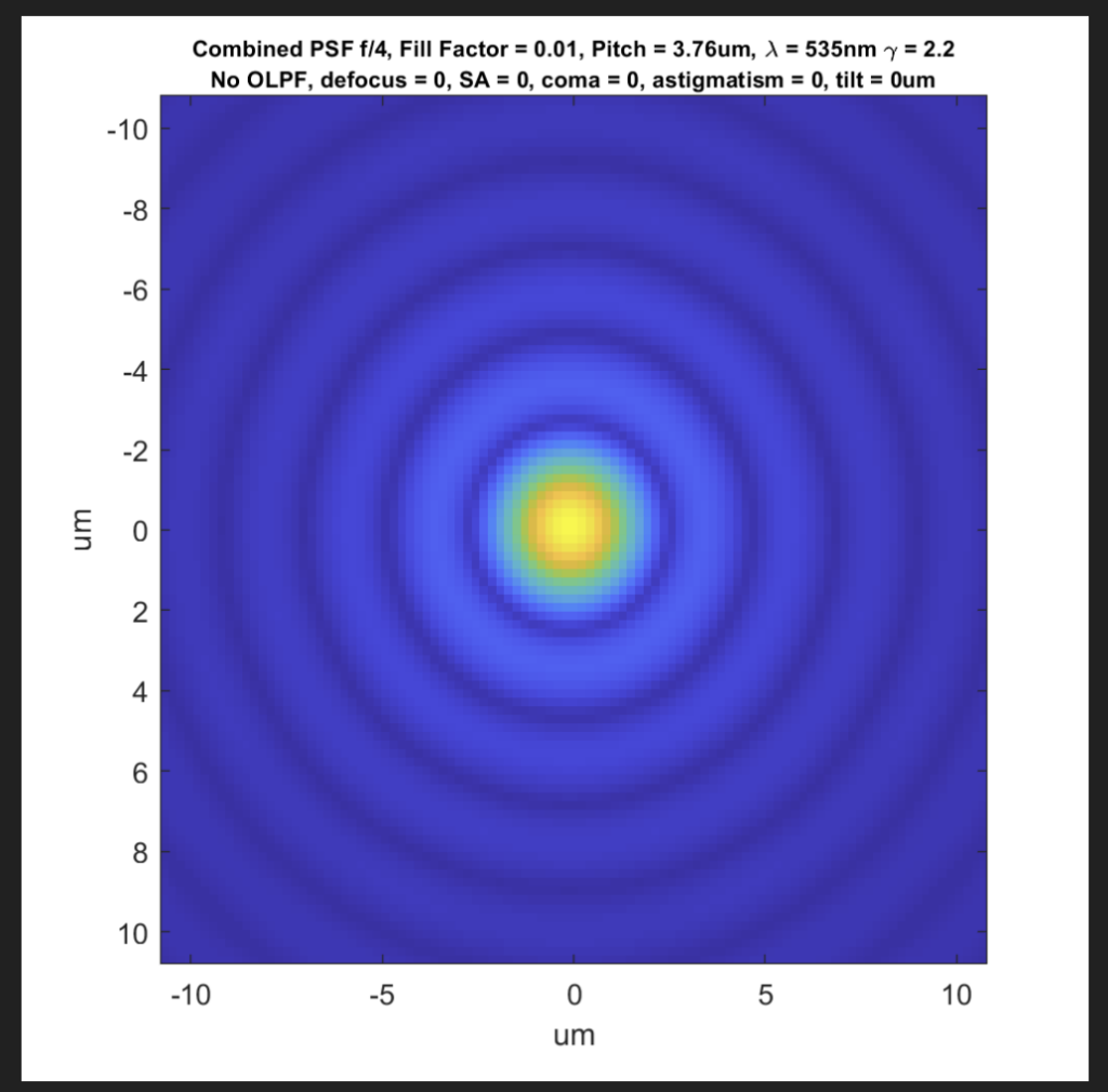
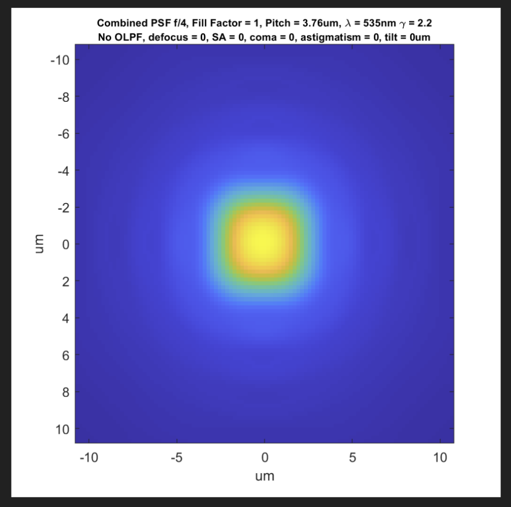
But camera sensors aren’t designed to be point samplers. In order to reduce aliasing and improve quantum efficiency, they sample areas approximately the size of the pixel pitch squared.
So a PSF with no AA filter looks like this:
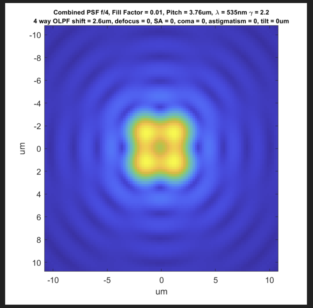
When you add a 4-shot AA filter, you get a PSF like this:
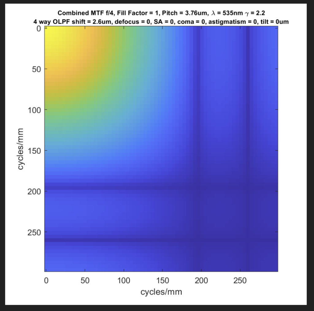
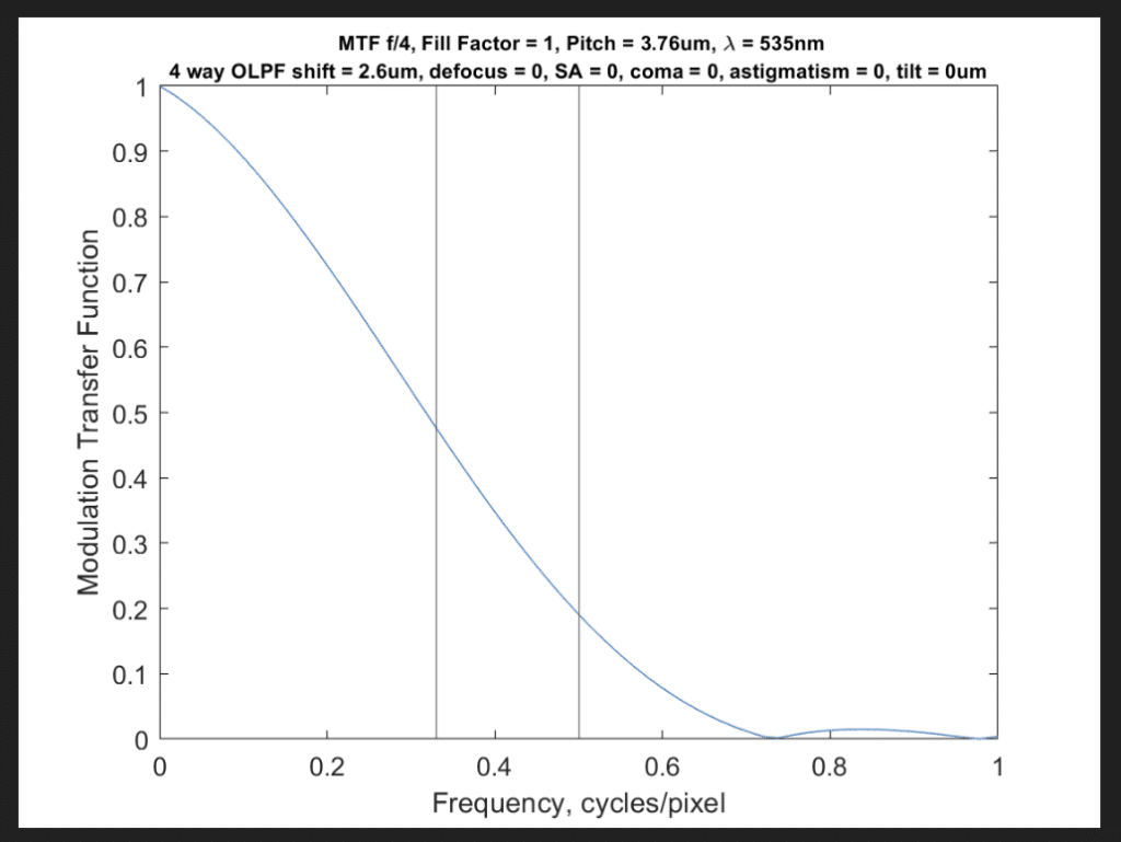
In the frequency domain, the combination of the AA filter and 100% fill factor looks like this:
There are two sets of zeros in both the horizontal and vertical directions. The first set (the one closest to the origin at the top-left of the graph) is caused by the OLPF and occurs about 0.7 cycles/pixel. The second set is caused by the pixel aperture, and occurs at about 1 cycle/pixel.
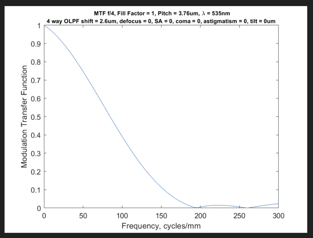
In one dimension, the MTF looks like this:
Since we’re concerned with aliasing, we can change the horizontal axis to cycles per pixel:
I’ve plotted vertical lines at the Nyquist frequency (half a cycle per pixel) and what I consider to be a useful approximation of the Nyquist frequency for sensors with a Bayer color filter array (a third of a cycle per pixel). Stricter reasoning would put the Nyquist frequency at a quarter the sampling frequency, since the red and blue raw channels are sampled at that frequency.
It’s clear from the theoretical graphs above that AA filters as currently designed can help reduce aliasing, but they’re not strong enough to eliminate it.
What about the contention above that AA filters introduce blur that makes the job of pixel shifting hardware and software less effective? In a word: that’s hogwash.
Lenses introduce blur. Fill factors of greater than 0% introduce blur. Diffraction introduces blur. Microlenses introduce blur.
Is anybody claiming that pixel shift doesn’t work right in the presence of diffraction? 100% fill factors? Lens aberrations? To my knowledge, they are not. There is no substance to the assertion that AA makes things more difficult for pixel shifting. I should point out that, given sufficient blur, aliasing won’t occur, and thus pixel shift is unnecessary, but that’s a corner case.
Now I’ll deal with the argument that camera manufacturers don’t use pixel shift on cameras that have AA filters because the combination is somehow incompatible. The above has been based on fact, but, since I don’t have knowledge of camera makers’ internal decision making process, I must speculate.
First, I’ll accept for the purposes of this discussion that no camera manufacturer uses pixel shift on cameras that have AA filters. I don’t know that that’s true, but I can’t think of any counterexamples.
Second, the transition from AA filters being the standard on FF cameras (to my knowledge, they have never been standard on medium format cameras) to not available on high-resolution FF cameras had great momentum well before IBIS-enabled pixel shift started to enjoy its present popularity. Nikon put a toe in the water when they offered the D810 with and without AA filtering, and the market voted so strongly that from then all all high resolution FF Nikon cameras had no AA filter. Sony introduced the a7R with no AA filter, and to my knowledge none of the R models since have had an AA filter. IBIS in FF cameras came along a bit later. IBIS is more important on high-resolution cameras than on low-res ones, so it made sense to introduce IBIS on the high-res cameras, which already had dropped their AA filters.
I decry the tendency for camera manufacturers to leave the AA filters out of their highest resolution cameras. The argument is that the resolution is high enough that there won’t be visible aliasing, but you just have to look at images from the GFX cameras, Sony 7Rx cameras, Hasselblad X series cameras, and the high-res Z cameras to know that that’s not the case. Why do high-res camera purchasers prefer cameras with no AA filters? I blame pixel peeping. If your objective is to have the crispest pixels when examined at 100% magnification, then you don’t want an AA filter. If your goal is to make the best prints, then I submit that you do. There will come a time when the pixel pitch of high res cameras is so great that there won’t be aliasing with the sharpest lenses at their best apertures, but my calculations are that we’ll need cameras with substantially more than 800 MP before that day arrives.
> IBIS in FF cameras came along a bit later.
incorrect, IBIS was present in Sony FF dSLRs and dSLTs way before dSLMs … A900 had it in 2008 for example
Thanks. My experience with IBIS began with MILCs, and I didn’t know about the earlier Sony cameras.
Hi Jim,
Thanks for this interesting article.
Microlenses introduce blur? In my opinion it’s quite the opposite. Microlenses increase MTF. No free lunch here because the negative side effect is that it will introduce discontinuities in the area in between the pixels.
Cheers
JaapD
If the effective receptive area of the microlens is larger than the underlying pixel, the microlens will reduce the MTF. If the effective receptive area of the microlens is smaller than the underlying pixel, the microlens will increase the MTF.
Would not leaving out AA filtering in ‘high-end’ cameras be a benefit, where any AA being desired can be done so with good post processing software? – Applied selectively, allowing more control over the final image.
Once the information is aliased, that process cannot be reversed in post production. All you can do is cover up the artifacts.