I have written many posts about managing depth of field (DOF). I have related DOF to modulation transfer function, and developed a way to deal with it from that perspective. I have written a DOF optimizer program that balances the effects of geometrical DOF, diffraction, and capture pixel blur. I have explained how focus stacking works, and how to get the most out of it.
But those have all been fairly to highly mathematical, and some people just can’t understand things from math. So this post is going to be different. Yes, it will have a bit of math. You can’t discuss DOF productively without math. But there will be plenty of visuals, too.
OK, what’s this all about? There is a group of people who believe that depth of field calculators are wrong when applied to medium format photography. They say that the difference in DOF between MF and FF photography is much greater than what is reflected in those calculators. I have been arguing for months now that the calculators are right, but that the circle of confusion (CoC) diameter entered into them must be appropriate for the judgement that will be made from the finished print or the screen.
The purpose of this post is to figure out what is the right CoC diameter to use for critical work. That means the largest CoC that will show no material effect in the final image. The context is landscape photography, the Fuji GFX 100 or GFX 100S cameras, and close viewing of large prints or 1:1 viewing on a display.
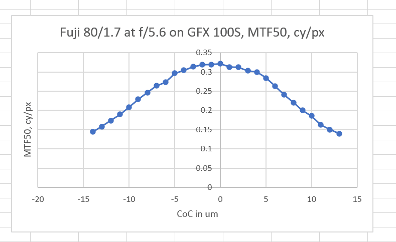
To start out, I used the GFX 100S focus bracketing feature to make a series of images of a Siemens star and a slanted edge with CoC diameters from misfocusing that were 2 micrometers (um) apart, making the worst-case CoC in the series half that, or 1 um. I used the Fuji 80 mm f/1.7 and a target distance of about 14 meters. I looked at the slanted edge with Imatest, and plotted the MTF50s:
The x-axis in the above plot is the worst-case CoC delta. I apologized for that. Absolute CoCs are twice that.
The vertical axis is MTF50 in cycles/pixel. The horizontal axis is the CoC from defocusing.
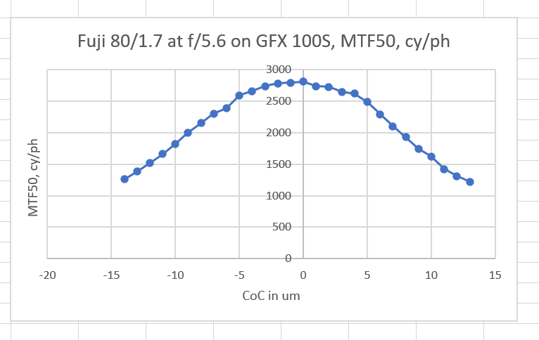
You are probably more used to seeing MTF50 in cycles per picture height. The above graph presents the data that way.
Notice that the top of the “haystack” is quite flat. There are four reasons for that.
- Defocus MTF effects are small for very small errors.
- Diffraction limits the peak levels for all displacements
- Lens aberrations limit the peak levels for all displacements
- The pixel aperture of the camera limits the peak levels for all displacements
It seems that CoCs diameters of 4 or 5 um have minimal effect on image sharpness.
Let’s look at the images themselves, first about 70% magnification:
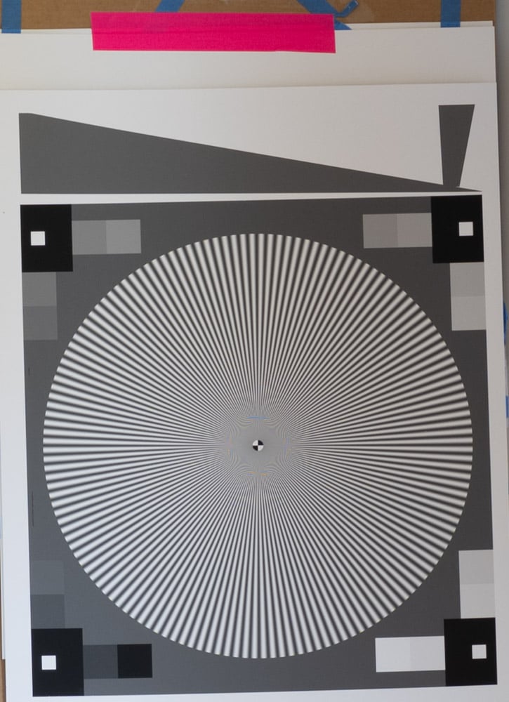
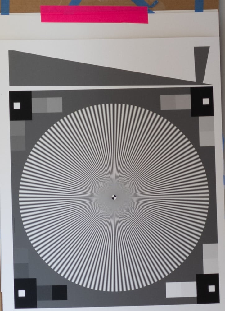
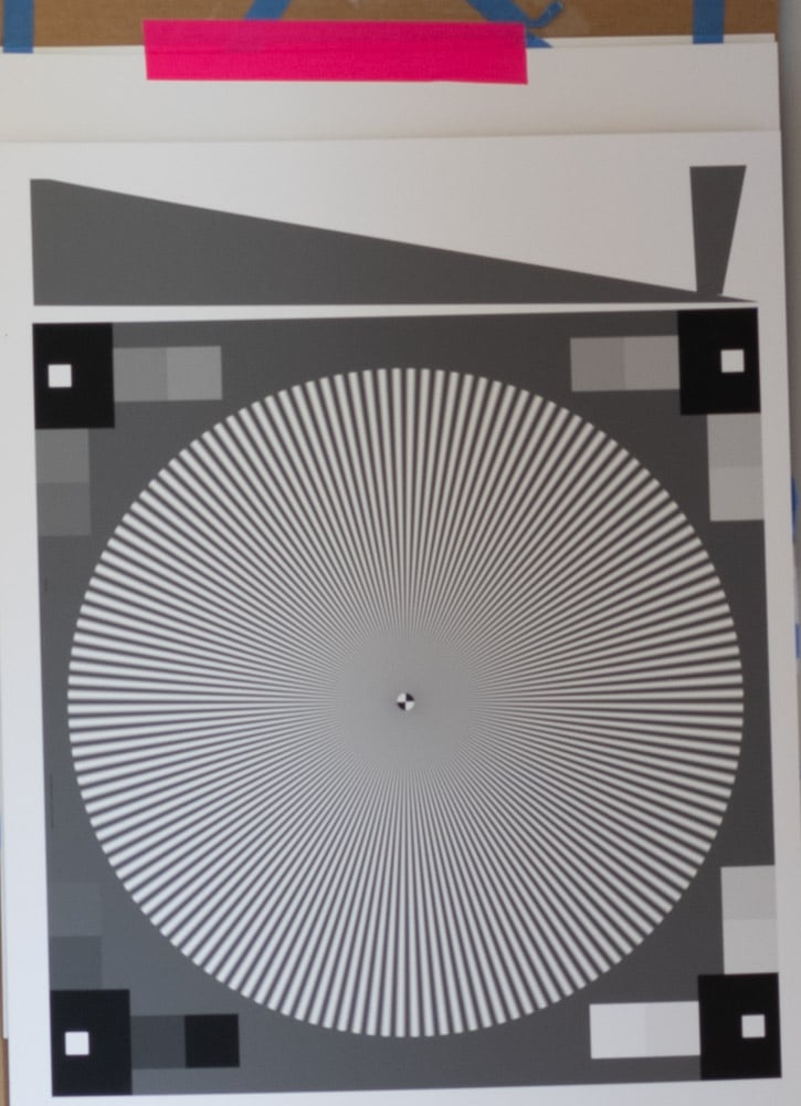
And now at about 160% magnification:
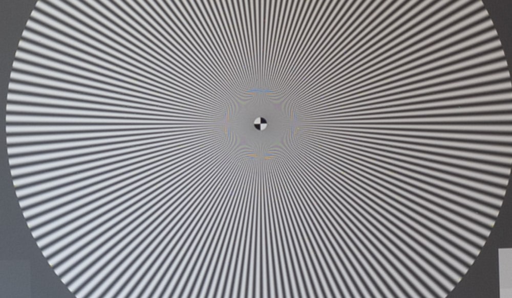
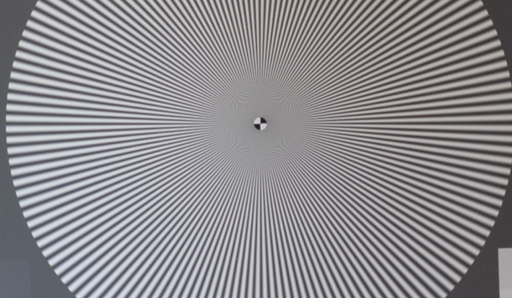
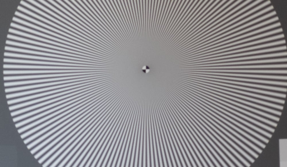
The way I see the images above, the CoC = 10 um image is still sharp(ish), but the CoC = 20 um image is not. This is probably close to a worst case scenarios for judging sharpness, since a Siemens star, even the sinusoidal version that I used above, is a very demanding target.
Now with some natural foliage, at 160% magnification:
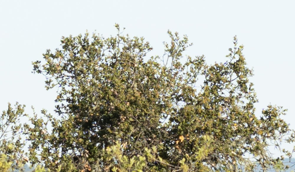
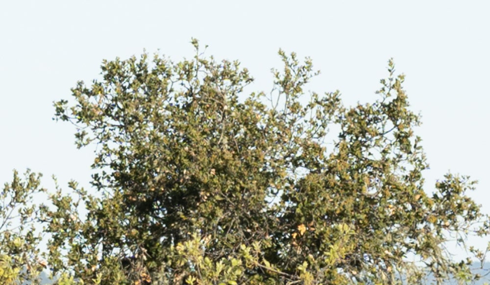
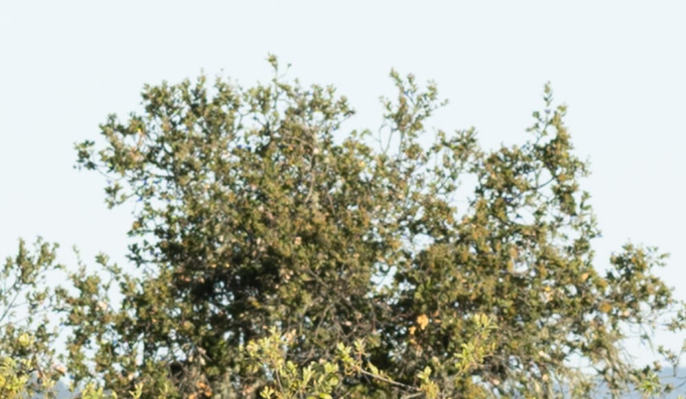
It’s not as cut and dried with a natural subject, but for me the answer is the same. A CoC of 5 um is on the threshold of critically sharp, and a CoC of 10 um is not.
If we zoom out a bit from the CoC = 0 image above:
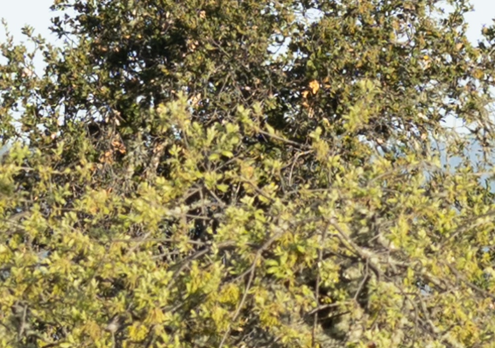
We can see that the tree in the top part of the image, which is the one focused on, is sharp. That tree is 101 meters away. The tree in front of it, which is 54 meters away, is not particularly sharp.
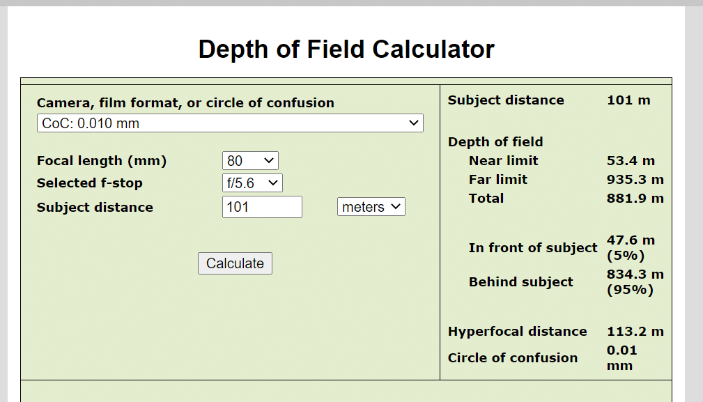
Firing up a standard DOF calculator:
With a 10 um CoC, the calculator says the 54-meter-distant tree will be barely within the CoC.
The good news is that DOF calculators work, although the one I used just know doesn’t include the effects of diffraction.
The bad news is that CoCs of 5 or 10 um will not give us much DOF. Optics is cruel sometimes.
RCone says
A major problem with discussions of Circle of Confusion (CoC) is that people’s definitions are not in agreement or, as for the general public’s, not even well founded.
Your discussion is valuable to me, since in much of my imaging, I am interested in capturing at ‘camera pixel resolution’ or as close to it as possible, sometimes in landscapes, more often in images with no depth that I am capturing for reference purposes and for potential use of small portions of “documents” – buildings, artifacts, paper, drawings.
The quantity you call CoC is a very useful one, but to me it is not a Circle of Confusion as traditionally defined. A traditional CoC is determined by consideration of lens and camera performance in conjunction with eye resolution limits in print or other image viewing. In the days of film, it took no consideration of the resolution of the film.
I would invent a new name for what you are calling CoC here, or at least give it a defining prefix. The old term “least circle of confusion,” while not appropriate here is an example of a useful prefix.
JimK says
There is a long history of using the term circle of confusion in conjunction with geometric optics to form a theoretical basis for depth of field discussions.
It is well explained here:
http://www.trenholm.org/hmmerk/TIAOOFe.pdf
The thrust of the article is towards object field methods, but the author does a good job of explaining image-field theory.
JimK says
Conventional DOF tables were derived using a CoC of between 30 and 40 um for FF cameras.
If you use an online DOF calculator like this one:
https://www.dofmaster.com/dofjs.html
you can enter your preferred CoC.
Ilya Zakharevich says
Jim, I find the absence of words “diameter” or “radius” very revealing! (Do not know what this reveals — but I cannot read this… :–(.
JimK says
The convention for CoC calculations is to enter the diameter of the circle. I’ll make that explicit.
Ilya Zakharevich says
Thanks! But I STILL cannot find it (even ran “Find in page” again…).
Joseph Holmes says
Jim, I’m just getting familiar with the GFX 100S “Focus Bracket” feature, and at this point, without having actually processed any test exposures in Helicon Focus, I’m getting the distinct impression from what I can see using the camera alone for EVF live view inspection and capture review that a step size of 10 is pretty ideal, i.e. not too coarse to get all distances well in focus, despite advice to the contrary. Is it not the case that given the plus or minus 5 micron range shown in your plot in this article and if we choose a Step size in the GFX tool of 10, that we should be staying within that attractive range, i.e. never more than 5 microns off the plane of focus? That would seem to be ideal, though closer inspection on a monitor may well indicate that 10 is nevertheless somewhat too coarse. Note that I would generally be using relatively small apertures (more stopped down).
I have found the GF 32-64 to be rather severely plagued by curvature of field, progressively worsening from 32mm all the way to 64mm, otherwise I would be less inclined to anticipate needing the Focus Bracket feature very often. The curvature is mild at 32, but substantially troubling by 45 and worse at 64. A few days ago I did a calculation to try to get a sense of the magnitude of the curvature in millidiopters compared with the thickness of the zone of good focus at f/11. I found the curvature to be only 6% of that thickness at 32mm, 10% at 45mm and 24% at 64mm. Even so, these fractions, in practice, at least from roughly 40mm on up, are sufficient to cause real trouble for me should I fail to get the entire image into focus. Assuming the top edge of an image is distant and the lower edge is close, the top corners are apt to be OOF from focussing too close there and the middle region of the lower edge is apt to be OOF from focussing too far there. Thus the wish to grab e.g. 3 to 5 frames instead of one as insurance at times. The manual version of the Focus Bracket tool is the more attractive of the two.
I’ve never had to rely on any lens with so much curvature in any of my outfits before, so this is presenting a learning opportunity. I would do without the zoom for this range if I could, but I need the flexibility of focal length that it brings. I’m hoping that the 45-100 I’ll be receiving tomorrow will do a better job of being flat between 45 and 64mm, though I know from seeing several samples from it which demonstrate that the corners at 45 will be significantly curved toward the camera that I’ll likely still not be thrilled with that important detail at 45mm.
JimK says
Joe, have you seen this?
https://blog.kasson.com/gfx-50s/how-focus-bracketing-systems-work/
For macro work, I usually use a step size of 5 or 7.
Joseph Holmes says
Thanks Jim, that’s about as rich an explanation as one could possibly hope for. When you wrote “The single-step CoC in um is twice the step size” that explained the situation. I thought I had read that the step size was equal to the CoC size, not double it. Thus the max CoC between the theoretically perfectly sharp planes would be half the step size instead of equal to it.
I’m thinking of landscape-scale work and I know there’s no substitute for trying a few all the way through the process, but that at least pulls me in the direction of smaller steps. By the time I add together my preference for higher-diffraction apertures for overcoming other issues and feeling OK about fairly strong deconvolution sharpening I may yet come down in favor of somewhat larger steps, 8 to 10, but I’ll just try it and see! I would want a strong sense of uniformity of image detail in the net result. Thanks again.