This is a continuation in a discussion of spatial frequency response (SFR) and modulation transfer function (MTF) testing reproduciblity. The series starts here:
The basic lighting technique that I’ve been using for my razor blade MTF testing has been to backlight a piece of white paper with two LED panels at a 45-degree angle to the paper. I put the razor blade a couple of feet in front of the white paper. There are two reasons for that. I want the paper well out of focus, and I don’t want any atray light falling on the front of the razor blade, which is supposed to be silhouetted against the paper.
From the Sony a7RII’s perspective, the setup looks like this:
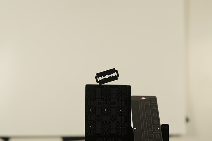
I use APS-C crop mode to save disk space and processing time. If you don’t, the razor blade will appear smaller in your pictures.
How sensitive are the MTF50 values derived from the above setup to lighting variations? That’s mostly what this post is about.
The Westcott LED panels that I use have two sets of LEDs: one with a color temperature of 2800 degrees Kelvin, amd one with a color temp of 6000K. On the controls there’s a dial that lets you set the temperature of the combined light. It operates by mixing varying amounts of the two kinds of LEDs. Intensity is not corrected for.
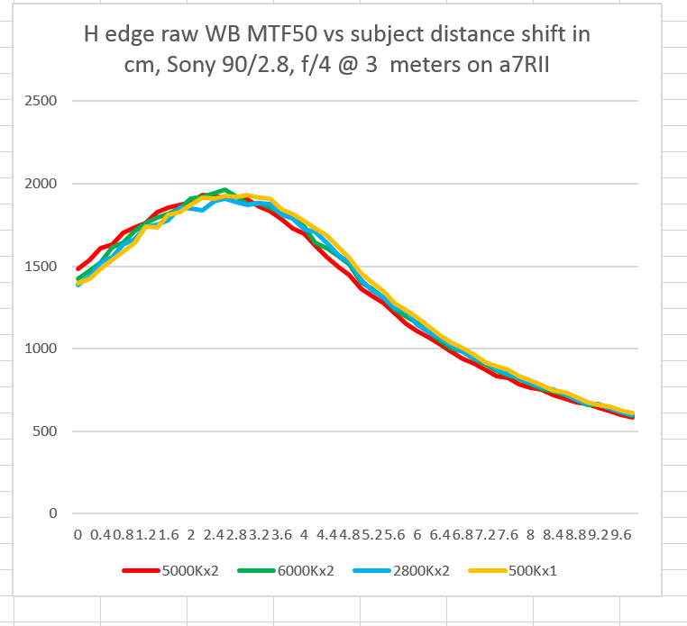
I set the panels to 2800K, 5000K, and 6000K, with lighting level to 100%, and made a series of 51 razor blade exposures at each color temperature with 2mm of travel between each exposure, and the Sony 90mm f/4 FE macro lens. The I turned off one of the LED panels and made another set of exposures at 5000K.
Here are the MTF50s of the three raw color planes:
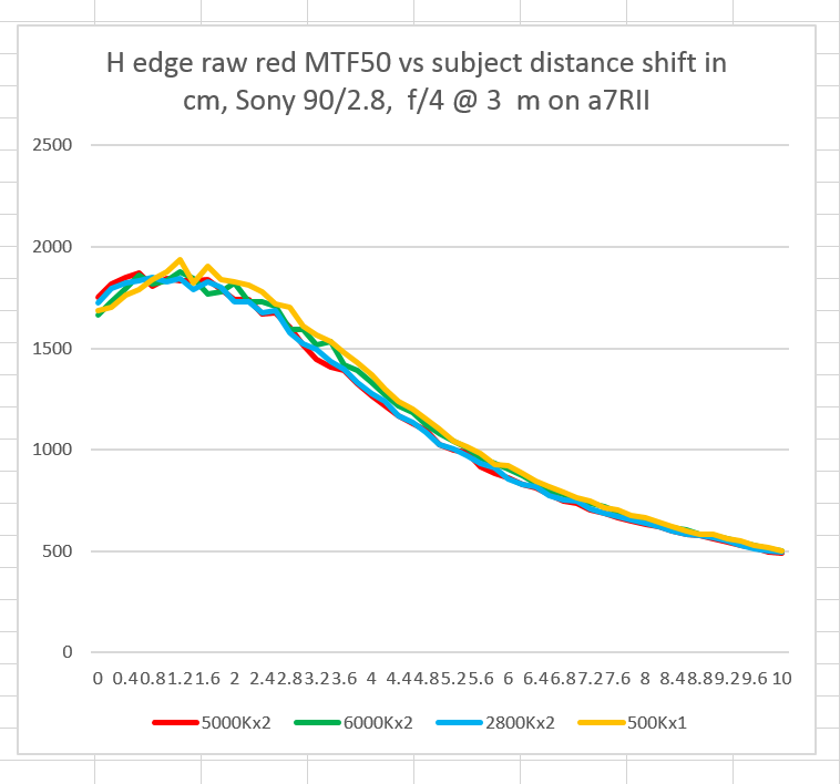
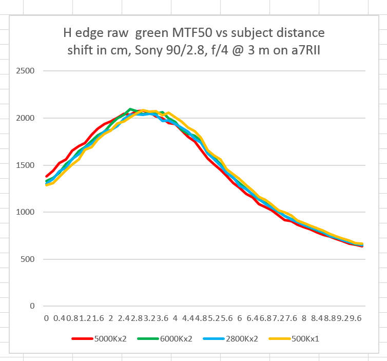
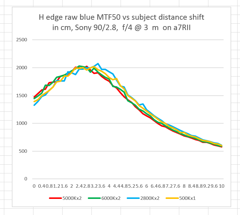
Distance is the horizontal axis, with the left hand size having the subject farther from the camera than the right hand side (The camera moves closer to the subject by 2 mm after each exposure). The vertical axis is MTF50, measured in cycles per picture height, assuming the entire sensor is used.
Here’s the white balanced MTF50 data:
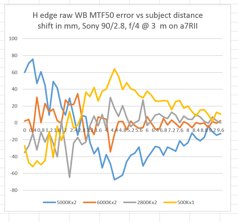
And the difference between the four test runs and the average of the four test runs at each distance:
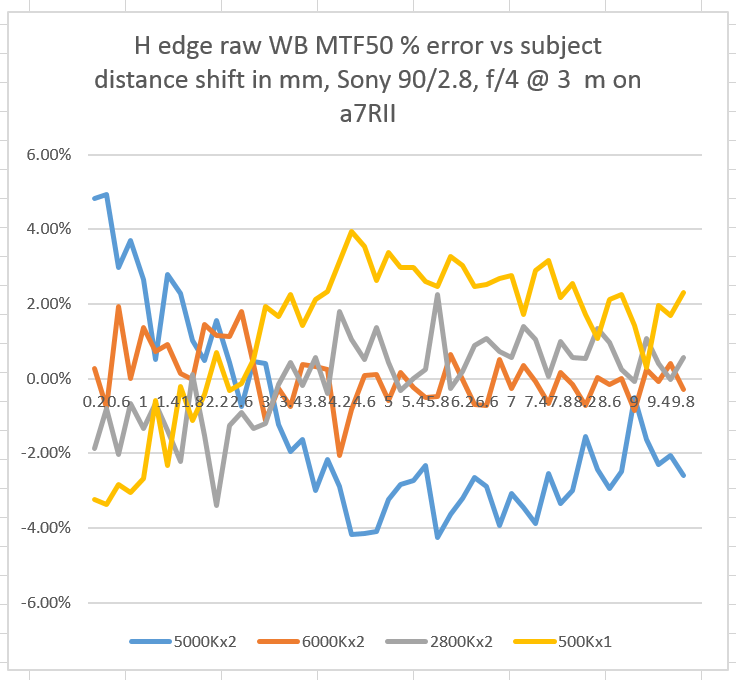
The above data expressed as a percentage error:
The errors appear to consist of a noise component that is unrelated to position, and which probably can be smoothed out, although at this point in the development of a protocol, I resist smoothing, as I think it can obscure underlying effects. For the two 5000K curves, there appears to be a systematic error that is position dependent (or maybe time-dependent), although it goes in opposite directions in the two curves.
At this point, I consider plus or minus 4% to be not bad accuracy, and I don’t think that lighting color temperature or geometry is particularly critical for this protocol.
I’ve been asked if flash illumination would be useful for this kind of testing. I see no reason why it wouldn’t work, but I have a few caveats.
If you use continuous illumination, you can, with proper exposure compensation, let the camera’s automatic exposure system control the shutter while you do the usual constant-aperture tests. This is a convenience, but I think the main advantage is the elimination of a class of experimental error. I suppose that, with TTL flash, that advantage doesn’t have to go away, but my studio strobes don’t support TTL, and I’ve never tried that.
You may find the situation different with small flashes, but I’ve found that I can’t turn my strobes down far enough to get wide open exposures with fast lenses, and I end up having to put diffusers in front of them. You might think that you can use bounce flash to throw away some photons, but I think it would be tricky to do that and not end up with stray light on the front of the razor blade.
Using flash also means that you can’t do runs that test the camera’s resistance to vibration-induced blurring.
If you do decide to use flash, I would recommend a flash with a short duration to mitigate any vibration that might occur. If your camera doesn’t offer EFCS, then flash in a dark room with a shutter speed of 1/2 second or slower and trailing curtain synch may be the only way you can deal with shutter vibrations.
Interesting the difference between 5000Kx1 and x2. Could be the effect of non uniform (gradient) illumination on the measurement.
I thought you weren’t supposed to use high-contrast targets for slanted edge MTF testing, but rather 1:4? Or so the imatest docs say: “The high contrast (≥40:1) recommended in the old ISO 12233:2000 standard produced unreliable results (clipping, gamma issues). The new ISO 12233:2014 standard recommends 4:1 contrast.”
In my own tests, I’ve not yet found the contrast to have a huge effect on MTF, but I’ve mostly tested with printed targets so far, which happen to have rather low contrast.
I’ve read that, too. When I do printed targets, I do them at low contrast. However, I don’t know of a reproducible way to do that with the razor blade. I have gotten repeatable results using the razor blade, and the Imatest edge curves show mo signs of clipping.
The 4:1 contrast recommendation seems to have been incorporated just to make it harder for clipping to occur with processed images. If one works with unclipped linear data the recommendation does not make much sense imho.