• site home
  • blog home
  • galleries
  • contact
  • underwater
  • the bleeding edge

the last word

Photography meets digital computer technology. Photography wins -- most of the time.

You are here: Home / a7RIV / Sony a7RIV self-heating read noise changes

Sony a7RIV self-heating read noise changes

September 15, 2019 JimK 20 Comments

This is one in a series of posts on the Sony alpha 7 R Mark IV (aka a7RIV). You should be able to find all the posts about that camera in the Category List on the right sidebar, below the Articles widget. There’s a drop-down menu there that you can use to get to all the posts in this series; just look for “A7RIV”.

The temperature of the sensor has an effect on read noise. This effect is greater for longer exposures. I ran some tests on the Sony a7RIV to quantify it. Both tests used about 128 dark-field exposures. The first was aimed at discovering short-term effects that applied to short exposures. I measured the rms noise in a 600×600 pixel patch just to the left of the center column for each of the raw channels:

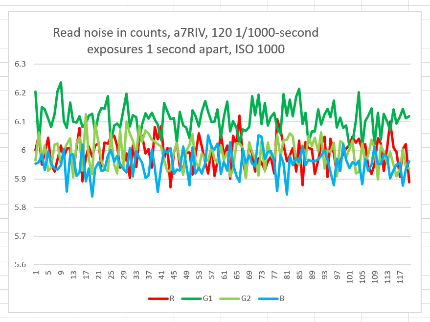
There aren’t any short term effects visible.

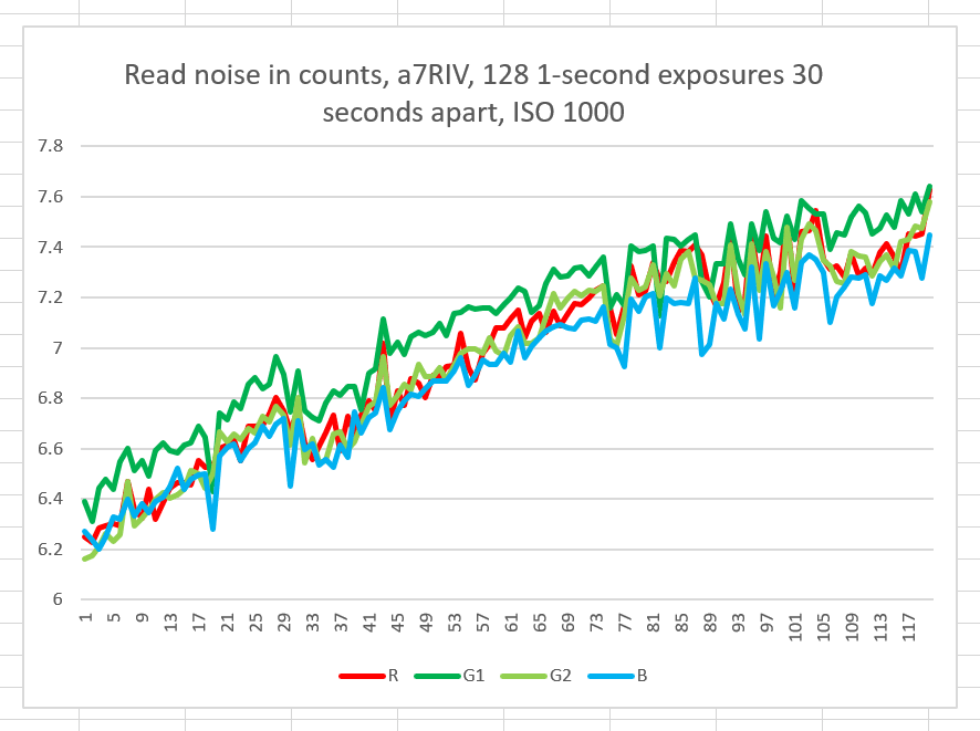
Then I made a sequence of 128 1-second exposures 30 seconds apart, with the LCD on the whole time, giving the camera more than an hour to warm up:


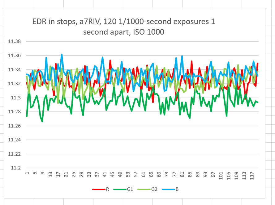
Here are the two curves expressed in terms of engineering dynamic range (EDR):

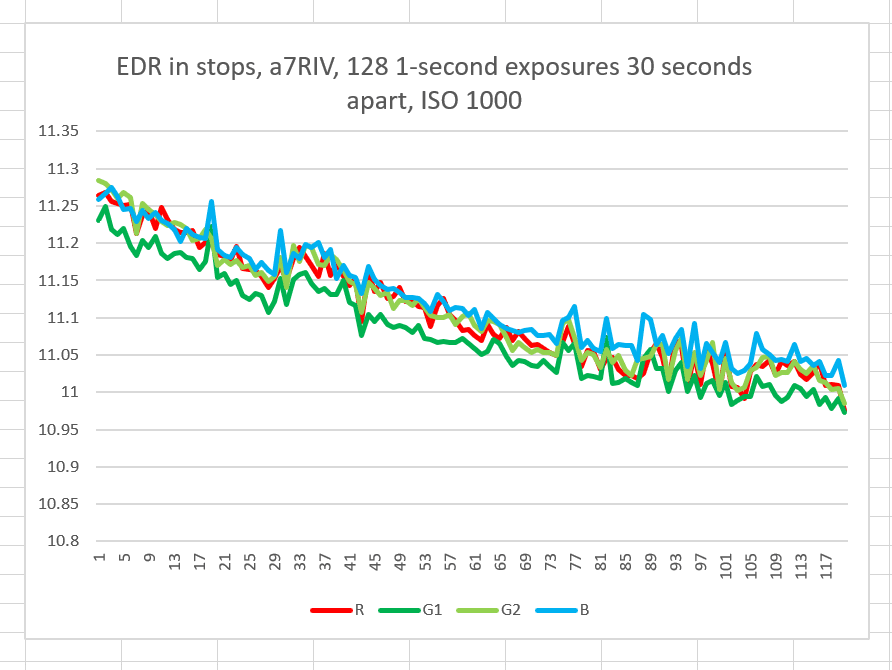
Overall, there is about a 0.2 stop change in EDR. That’s not enough to worry about.


a7RIV

← Sony a7RIV raw histograms Sony a7RIV fixed-pattern read noise — short exposures →

Comments

  1. Frans Waterlander says

    September 18, 2019 at 12:13 pm

    Sensor heating caused by photodiode current is tiny compared to sensor heating caused by all the other circuitry. For the GFX 100 you calculated >200mW. So, self heating is worst when the sensor is the most active, like in Live View or video mode. Was the camera in stand-by mode (not active) in between the shots? If so, then self heating would be minimal.

    Reply
    • JimK says

      September 18, 2019 at 12:21 pm

      Was the camera in stand-by mode (not active) in between the shots?

      No.

      Reply
    • JimK says

      September 18, 2019 at 12:21 pm

      Sensor heating caused by photodiode current is tiny compared to sensor heating caused by all the other circuitry. For the GFX 100 you calculated >200mW

      I did nothing of the kind.

      You can calculate the photodiode current approximately: take the FWC, multiply it by the number of pixels, multiply by 1.602 * 10^−19, and divide by the exposure time.

      For the GFX 100 and 1/100th second scan time, which is very fast, that’s 1.02E8 * 47000 * 1.602E-19 * 100, or 7.6800e-05 amps. With a 5w power supply, which is probably high, that’s 3.8400e-04 watts, or about a third of a mw.

      Reply
      • Frans Waterlander says

        September 19, 2019 at 12:32 pm

        I intended to say that you previously calculated the photo diode power dissipation for the GFX 100 to be >200mW.

        Reply
        • Frans Waterlander says

          September 19, 2019 at 12:35 pm

          Something very weird is going on with your comments program. My 12:32 pm comments are not what I wrote. Words got deleted.

          Reply
        • JimK says

          September 19, 2019 at 12:44 pm

          I did not calculate a number anywhere near that high.

          Reply
          • Frans Waterlander says

            September 19, 2019 at 3:17 pm

            I’ll try one more time. Please note that in 2 previous replies words got droppen. What I wanted to say is that in the past you calculated >200mW.

            Reply
            • Frans Waterlander says

              September 19, 2019 at 3:18 pm

              That’s not what I just typed!!! Your calc was >200mW.

              Reply
              • Frans Waterlander says

                September 19, 2019 at 3:18 pm

                Again words are dropped. Are you paying any attention?

                Reply
                • Frans Waterlander says

                  September 19, 2019 at 3:20 pm

                  Last try!
                  Your photo diode calc was >200mW.
                  Let’s see if more words are lost.

                • JimK says

                  September 19, 2019 at 3:24 pm

                  It was not. It was a few hundred microwatts under some pessimistic assumptions.

                • JimK says

                  September 19, 2019 at 3:21 pm

                  What words were dropped?

            • JimK says

              September 19, 2019 at 3:20 pm

              I didn’t.

              Reply
              • Frans Waterlander says

                September 19, 2019 at 3:21 pm

                Your comments machine is totally our of whack and drops many words or you are playing games.

                Reply
                • JimK says

                  September 19, 2019 at 3:22 pm

                  No one else has complained.

                • JimK says

                  September 19, 2019 at 3:29 pm

                  If you can’t make my blog work to your satisfaction, post your questions on DPRs Sony alpha full frame forum, and I’ll deal with it there.

              • Frans Waterlander says

                September 19, 2019 at 3:37 pm

                On August 22 you emailed me and estimated <= 1uA at 5V or <=5uW.
                On August 23 you corrected that to <100nA or <0.5uW.

                My estimate of total power 200mW or more.

                Reply
                • JimK says

                  September 19, 2019 at 5:22 pm

                  If I said that, under one set of assumptions, total current was less than 1 ua, and power less than 5 uW, then said it’s probably even lower, how do you figure I said total power was more than 200 milliwatt? Makes no sense to me.

                • Frans Waterlander says

                  September 22, 2019 at 2:32 pm

                  The >>200mW is my guestimate of total sensor power dissipation based on the fact that Sony sensor data sheets lowest value for power dissipation is 160mW for a 5MP sensor. Therefore, the lions share of sensor heating is caused by total sensor power dissipation, not photo diode current.

                • JimK says

                  September 22, 2019 at 2:38 pm

                  I certainly agree that the lions share of sensor heating is caused by total sensor power dissipation, not photo diode current.

Leave a Reply Cancel reply

Your email address will not be published. Required fields are marked *

May 2025
S M T W T F S
 123
45678910
11121314151617
18192021222324
25262728293031
« Apr    

Articles

  • About
    • Patents and papers about color
    • Who am I?
  • How to…
    • Backing up photographic images
    • How to change email providers
    • How to shoot slanted edge images for me
  • Lens screening testing
    • Equipment and Software
    • Examples
      • Bad and OK 200-600 at 600
      • Excellent 180-400 zoom
      • Fair 14-30mm zoom
      • Good 100-200 mm MF zoom
      • Good 100-400 zoom
      • Good 100mm lens on P1 P45+
      • Good 120mm MF lens
      • Good 18mm FF lens
      • Good 24-105 mm FF lens
      • Good 24-70 FF zoom
      • Good 35 mm FF lens
      • Good 35-70 MF lens
      • Good 60 mm lens on IQ3-100
      • Good 63 mm MF lens
      • Good 65 mm FF lens
      • Good 85 mm FF lens
      • Good and bad 25mm FF lenses
      • Good zoom at 24 mm
      • Marginal 18mm lens
      • Marginal 35mm FF lens
      • Mildly problematic 55 mm FF lens
      • OK 16-35mm zoom
      • OK 60mm lens on P1 P45+
      • OK Sony 600mm f/4
      • Pretty good 16-35 FF zoom
      • Pretty good 90mm FF lens
      • Problematic 400 mm FF lens
      • Tilted 20 mm f/1.8 FF lens
      • Tilted 30 mm MF lens
      • Tilted 50 mm FF lens
      • Two 15mm FF lenses
    • Found a problem – now what?
    • Goals for this test
    • Minimum target distances
      • MFT
      • APS-C
      • Full frame
      • Small medium format
    • Printable Siemens Star targets
    • Target size on sensor
      • MFT
      • APS-C
      • Full frame
      • Small medium format
    • Test instructions — postproduction
    • Test instructions — reading the images
    • Test instructions – capture
    • Theory of the test
    • What’s wrong with conventional lens screening?
  • Previsualization heresy
  • Privacy Policy
  • Recommended photographic web sites
  • Using in-camera histograms for ETTR
    • Acknowledgments
    • Why ETTR?
    • Normal in-camera histograms
    • Image processing for in-camera histograms
    • Making the in-camera histogram closely represent the raw histogram
    • Shortcuts to UniWB
    • Preparing for monitor-based UniWB
    • A one-step UniWB procedure
    • The math behind the one-step method
    • Iteration using Newton’s Method

Category List

Recent Comments

  • JimK on Goldilocks and the three flashes
  • DC Wedding Photographer on Goldilocks and the three flashes
  • Wedding Photographer in DC on The 16-Bit Fallacy: Why More Isn’t Always Better in Medium Format Cameras
  • JimK on Fujifilm GFX 100S II precision
  • Renjie Zhu on Fujifilm GFX 100S II precision
  • JimK on Fuji 20-35/4 landscape field curvature at 23mm vs 23/4 GF
  • Ivo de Man on Fuji 20-35/4 landscape field curvature at 23mm vs 23/4 GF
  • JimK on Fuji 20-35/4 landscape field curvature at 23mm vs 23/4 GF
  • JimK on Fuji 20-35/4 landscape field curvature at 23mm vs 23/4 GF
  • Ivo de Man on Fuji 20-35/4 landscape field curvature at 23mm vs 23/4 GF

Archives

Copyright © 2025 · Daily Dish Pro On Genesis Framework · WordPress · Log in

Unless otherwise noted, all images copyright Jim Kasson.