This is a continuation of a series of posts about blur management for landscape photography. The series starts here.
Here’s a situation in which many landscape photographers often find themselves:
- There are important objects at various distances from the camera.
- There is too much subject motion to be able to use focus stacking or stitching techniques.
- There is not enough DOF available at low-diffraction apertures for all the objects to be sufficiently sharp at those stops.
- The photographer is uncertain what f-stop to pick and at what distance to focus in order to maximize the sharpness of the important objects.
I wrote a program to assist in the aperture and focus distance decisions. It takes the code that produced the graphs in the previous post, plus two additional set of information:
- A list of the distances at which the important subjects reside.
- A list of weights that describe the relative importance of those subjects.
The program spits out the optimum f-stop and focus distance, and plots the sharpness of those settings as a function of distance. As before, diffraction and DOF are considered, but not lens aberrations.
Let’s take it for a spin. If we put a 63 mm lens on a GFX 50S, at tell it that we have equally important subjects at 10 and 100 meters, here’s what we get:
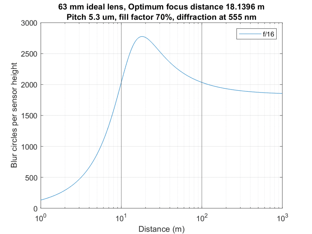
The two vertical lines mark the distances of the important parts of the image. F/16 is the optimum f-stop. That is deep into diffraction blur territory, and the resultant sharpness at 10 and 100 meters isn’t great, but anything wider — and anything narrower — would be worse.
This graph puts the lie to a couple of hoary rules of thumb:
- You should focus a third of the way from the closest thing you want sharp to the furthest.
- You shouldn’t use apertures where there is a lot of diffraction blur.
Once you decide to shoot at f/16, you could compute the distance to focus using conventional DOF calculators, but you wouldn’t have a sharpness metric that took diffraction into account.
Now let’s add a third distance, leaving the weights all the same:
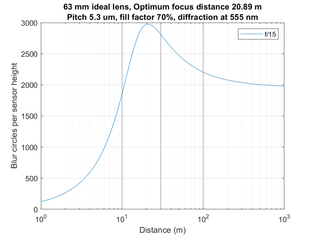
That moves the optimum focal point a bit further away, and says we can open up the lens fractionally. The differences are immaterial to real-world photography.
If we double the weight of the closest part of the subject:
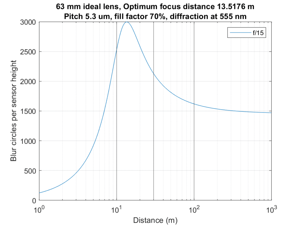
About what you’d expect.
Next up: taking the optimizer out into the world.
Thanks a lot for this very interesting series of posts! This is a really relevant topic.
I have one hint and some comments.
Hint
There is an iPhone app called OptimumCS-Pro, developed by George Douvos (see http://www.georgedouvos.com/) which allows you to do a comparable optimization in the field. You can enter the focal length as well as the nearest and the farthest distance and it calculates the optimum focusing distance and f-stop as well as the blur spot diameter at the nearest and farthest distances, taking diffraction into account. This is less than you do, there is no plot of the blur spot diameter over distance, it doesn’t even tell you the blur spot diameter at the focusing distance, and you can only enter two distances, but it is very intuitive and easy to use in the field.
I don’t know the math behind this app, and it seems to be a little different from yours, since it gives slightly different results. Using your example of an f=63 mm lens with the nearest distance at 10 m and the farthest at 100 m it calculates 18.2 m for the focusing distance (which is pretty close to yours), an f-stop of f/11 (instead of f/16) and a blur spot diameter of about 21 Microns (which I cannot compare, see second comment below). So, who is right – we don’t know.
Comments
• The absolute blur spot diameter given in Microns should depend only on the lens parameters, not on the sensor parameters. But your plots are given for a specific pixel pitch and fill factor of the sensor. I do not understand this.
• For me the absolute blur spot diameter is quite an intuitive value and metric to calculate. Even more intuitive would be the ratio of the absolute blur spot diameter to the pixel pitch of the sensor, although this would result in a sensor specific calculation with one more parameter. But your “blur circles per sensor height” metric is not intuitive at all (for me) and I failed in converting the blur circles per sensor height value to an absolute blur spot diameter for your example above. I don’t care for the sensor height, I only care for the pixel pitch when it comes to sharpness.
• I find it difficult to intuitively understand the optimization for more than two distances and even more so with different weights. Three distances can never have the same sharpness, so, what do I ask the optimization to do? And what does a weight of 2 for one distance mean compared to a weight of 1 for the other distances? Should points at this distance be twice as sharp as the ones at the other distances, i.e. with half the blur spot diameter? Probably you do a kind of least squares optimization with different weights for the different distances but this has no intuitive relation in the field – at least I am not able to see it. Maybe you can give us a hint on how to interpret this.
I take into account the blur introduced by the sampling aperture on the sensor. That’s why fill factor and pitch are necessary inputs.
Ok, understood.
This is definitely not taken into account in George Douvos’s app. But does this explain the different results using your example, i.e. a full stop difference for the optimum f-stop?
Don’t know. What does he round to? I round to integers for f-stops > 10.0.
When making same size prints from various sized sensors, computing blur diameters per picture height levels the playing field, much the same way as computing MTF50 in cycles per picture height does.
I have to admit I need to do some research to understand this, but thanks for the hint.
It levels what playing field? Are you perhaps attempting to equalize quality of print regardless of image-sensor size?
I’m trying to take sensor size out of the picture as much as I can, concentrating on what is visible in the print.
Let’s see if I understand.
If I use your technique twice, first with an APSC camera, then a full-frame camera with a lens of the same focal length, and if I select the same laser-measured distances and weights for your formula both times (to select aperture and focus distance), will the result (assuming perfect lenses with the same pixel pitch) of both prints be the same if object sizes are the same in both prints, but the full-frame print will have more coverage?
If so, it sounds like your concentration on “what is visible in the print” ignores viewing distance. It sounds to me like the right way to do it. There’s no reason to say that a larger print precludes a close look. If I cut piece out from a print, the quality of that piece of the print hasn’t changed.
Yes.
I do indeed minimize a cost function that is the sum of the weighted squared errors at each distance. The optimizer isn’t very accurate at distances less than 10 times the focal length of the lens, but consider a portrait. I’d weight the eyes heavily, and the forehead and lips less, and the shoulders even less.
Ok, lets take your portrait example, which I think is a good one.
I want maximum sharpness of the eyes (so I know in advance that I must focus on the eyes), I want reasonable sharpness of the lips, and there is a little tattoo on the cheekbone, which should be sharp as well, but doesn’t need to have optimum sharpness. How do I tell this to your optimizer — without using trial and error?
I think that you may not want to focus on the eyes, but just weight them more heavily. If you’ve already decided to focus on the eyes, then the optimizer won’t work as designed: it needs to vary both focus position and aperture. I think, after using the optimizer for a while, you can get a sense of the right weights for your situation. The fact that it shows you sharpness vs subject distance as part of its solution means that you can see how sharp things are at the various distances that you’ve specified. In your situation, I’d give the eyes a weight of 4, the lips 2, and the tattoo 1, run a pass and see what happens.
In your cost function, what is your formula for errors?
The error metric is blur circle size. There is a lot more on the specifics of that in subsequent posts.
Jim wrote, “The optimizer isn’t very accurate at distances less than 10 times the focal length of the lens.” That surprises me. What makes it less accurate at these shorter distances?
I used the thin lens equation, which is not accurate with modern lenses focused closely. I also ignored lens extension, and floating-element induced focal length changes with focused distance.
Thanks. In what way did you ignore lens extension? Lens extension is already accounted for in the thin lens equation, correct?
I ignored the fact that effective f-stop changes with focused distance.